80x86 Port with Emulated FP Support
- Former user (Deleted)
- WES Admin
- Former user (Deleted)
Real Mode, Large Model with Emulated Floating-Point Support
This chapter describes how µC/OS-II has been ported to the Intel 80x86 series of processors running in real mode, large model for the Borland C++ V4.51 tools. This port assumes that your application will not be doing any floating-point math or, if it does, it will use the Borland Floating-Point Emulation library. In other words, I assumed that you would use this port with embedded 80186, 80286, 80386 or even ‘plain’ 8086 class processors which rely only on integer math. This port can also be adapted (i.e., changed) to run ‘plain’ 8086 processors but requires that you replace the use of the PUSHA instruction with the proper number of PUSH instructions.
The Intel 80x86 series includes the 80186, 80286, 80386, 80486, Pentiums™ (all models), Celeron as well most 80x86 processors from AMD, NEC (V-series), and others. Literally millions of 80x86 CPUs are sold each year. Most of these end up in desktop computers, but a growing number of processors are making their way into embedded systems.
Most C compilers that support 80x86 processors running in real mode offer different memory models, each suited for a different program and data size. Each model uses memory differently. The large model allows your application (code and data) to reside in a 1Mb memory space. Pointers in this model require 32 bits, although they only address up to 1Mb. The next section shows why a 32-bit pointer in this model can only address 20 bits worth of memory.
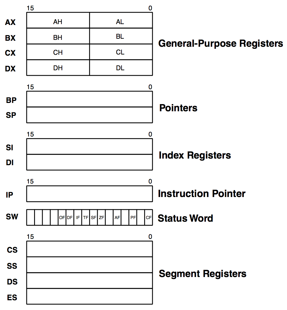
Figure 14.1 shows the programming model of an 80x86 processor running in real mode. All registers are 16 bits wide, and they all need to be saved during a context switch. As can be seen, there are no floating-point registers since these are emulated by the Borland compiler library using the integer registers.
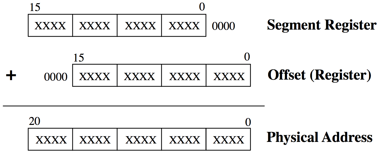
The 80x86 provides a clever mechanism to access up to 1Mb of memory with its 16-bit registers. Memory addressing relies on using a segment and an offset register. Physical address calculation is done by shifting a segment register by four (multiplying it by 16) and adding one of five other registers (BP, SP, SI, DI, or IP). The result is a 20-bit address that can access up to 1Mb. Figure 14.2 shows how the registers are combined. Each segment points to a block of 16 memory locations called a paragraph. A 16-bit segment register can point to any of 65,536 different paragraphs of 16 bytes and thus address 1,048,576 bytes. Because the offset is also 16 bits, a single segment of code cannot exceed 64Kb. In practice, however, programs are made up of many smaller segments.
The code segment register (CS) points to the base of the program currently executing, the stack segment register (SS) points to the base of the stack, the data segment register (DS) points to the base of one data area, and the extra segment register (ES) points to the base of another area where data may be stored. Each time the CPU needs to generate a memory address, one of the segment registers is automatically chosen and its contents is added to an offset. It is common to find the segment-colon-offset notation in literature to reference a memory location. For example, 1000:00FF represents physical memory location 0x100FF.
Development Tools
I used the Borland C/C++ V4.51 compiler along with the Borland Turbo Assembler to port and test the 80x86 port. This compiler generates reentrant code and provides in-line assembly language instructions that can be inserted in C code. The compiler comes with a floating-point emulation library that simulates the floating-point hardware found on 80x86 processors equipped with floating-point hardware. Once compiled, the code is executed on a PC. I tested the code on a 300 MHz Pentium-II-based computer running the Microsoft Windows 2000 operating system. In fact, I configured the compiler to generate a DOS executable which was run in a DOS window.
I thought of changing compilers because some readers have complained that they can’t find the Borland tools anymore which makes it harder to build the example code provided in this book. It turns out that a similar compiler and assembler that will compile the example code is in fact available from Borland for only $70 USD (circa 2002). Borland calls it the Turbo C++ Suite for DOS and you can order a copy by visiting the Borland web site at www.Borland.com and follow the links to this product.
You can also get professional 80x86 level tools from Paradigm (www.DevTools.com) that contains not only a Borland compatible compiler and assembler but also an IDE (Integrated Development Environment), a utility that will allow you to locate your code for deployement in embedded systems, a source level debugger and more. Paradigm calls their package the Paradigm C++ Professional Real.
Finally, you can also adapt the port provided in this chapter to other 80x86 compiler as long as they generate real-mode code. You will most likely have to change some of the compiler options and assembler directives if you use a different development environment.
Table 14.1 shows the Borland C/C++ compiler V4.51 options (i.e., flags) supplied on the command line. These settings were used to compile the port as well as the example code provided in Chapter 1.
| Option (i.e., setting) | Description |
|---|---|
| -1 | Generate 80186 code |
| -B | Compile and call assembler |
| -c | Compiler to .OBJ |
| -G | Select code for speed |
| -I | Path to compiler include files is C:\BC45\INCLUDE |
| -k- | Standard stack frame |
| -L | Path to compiler libraries is C:\BC45\LIB |
| -ml | Large memory model |
| -N- | Do not check for stack overflow |
| -n..\obj | Path where to place object files is ..\OBJ |
| -O | Optimize jumps |
| -Ob | Dead code elimination |
| -Oe | Global register allocation |
| -Og | Optimize globally |
| -Oi | Expand common intrinsic functions inline |
| -Ol | Loop optimization |
| -Om | Invariant code motion |
| -Op | Copy propagation |
| -Ov | Induction variable |
| -v | Source debugging ON |
| -vi | Turn inline expansion ON |
| -wpro | Error reporting: call to functions with no prototype |
| -Z | Suppress redundant loads |
Table 14.2 shows the Borland Turbo Assembler V4.0 options (i.e., flags) supplied on the command line. These settings were used to assemble the port’s OS_CPU_A.ASM.
| Option (i.e., setting) | Description |
|---|---|
/MX | Case sensitive on globals |
/ZI | Full debug info |
/O | Generate overlay code |
Directories and Files
The installation program provided on the companion CD installs the port for the Intel 80x86 (real mode, large model) on your hard disk. The port is found under the \SOFTWARE\uCOS-II\Ix86L\BC45 directory. The directory name stands for I ntel 80 x86 real mode, L arge model and is placed in the B orland C ++ V 4 . 5 x directory. The source code for the port is found in the following files: OS_CPU.H , OS_CPU_C.C , and OS_CPU_A.ASM .
INCLUDES.H
INCLUDES.H is a master include file and is found at the top of all .C files. INCLUDES.H allows every .C file in your project to be written without concern about which header file is actually needed. The only drawbacks to having a master include file are that INCLUDES.H may include header files that are not pertinent to the actual .C file being compiled and the compilation process may take longer. These inconveniences are offset by code portability. You can edit INCLUDES.H to add your own header files, but your header files should be added at the end of the list. Listing 14.1 shows the contents of INCLUDES.H for the 80x86 port.
INCLUDES.H is not really part of the port but is described here because it is needed to compile the port files.
#include    <stdio.h>
#include    <string.h>
#include    <ctype.h>
#include    <stdlib.h>
#include    <conio.h>
#include    <dos.h>
#include    <math.h>
#include    <setjmp.h>

#include    "os_cpu.h"
#include    "os_cfg.h"
#include    "ucos_ii.h"
#include    "pc.h"
OS_CPU.H
OS_CPU.H contains processor- and implementation-specific #defines constants, macros, and typedefs. OS_CPU.H for the 80x86 port is shown in Listing 14.2.
OS_CPU_GLOBALS and OS_CPU_EXT allows us to declare global variables that are specific to this port (described later).
#ifdef  OS_CPU_GLOBALS
#define OS_CPU_EXT
#else
#define OS_CPU_EXT  extern
#endif

typedef unsigned char  BOOLEAN;                  (1)
typedef unsigned char  INT8U;
typedef signed   char  INT8S;
typedef unsigned int   INT16U;
typedef signed   int   INT16S;
typedef unsigned long  INT32U;
typedef signed   long  INT32S;
typedef float          FP32;                     (2)
typedef double         FP64;

typedef unsigned int   OS_STK;                   (3)
typedef unsigned short OS_CPU_SR;                (4)

#define BYTE           INT8S                     (5)
#define UBYTE          INT8U
#define WORD           INT16S
#define UWORD          INT16U
#define LONG           INT32S
#define ULONG          INT32U
(1) If you were to consult the Borland compiler documentation, you would find that an int is 16 bits and a long is 32 bits.
(2) Floating-point data types are included even though µC/OS-II doesn’t make use of floating-point numbers.
(3) A stack entry for the 80x86 processor running in real mode is 16 bits wide; thus, OS_STK is declared accordingly. All task stacks must be declared using OS_STK as its data type.
(4) The status register (also called the processor flags) on the 80x86 processor running in real mode is 16 bits wide. The OS_CPU_SR data type is used only if OS_CRITICAL_METHOD is set to 3 which it isn’t for this port. I included the OS_CPU_SR data type anyway, in case you use a different compiler and need to used OS_CRITICAL_METHOD #3.
(5) I also included data types to allow for backward compatibility with older µC/OS V1.xx applications. These are not necessary if you don’t have any applications written with µC/OS V1.xx.
OS_CPU.H, OS_ENTER_CRITICAL() and OS_EXIT_CRITICAL()
#define  OS_CRITICAL_METHOD    2                          (6)

#if      OS_CRITICAL_METHOD == 1
#define  OS_ENTER_CRITICAL()  asm  CLI                    (7)
#define  OS_EXIT_CRITICAL()   asm  STI
#endif

#if      OS_CRITICAL_METHOD == 2
#define  OS_ENTER_CRITICAL()  asm {PUSHF; CLI}            (8)
#define  OS_EXIT_CRITICAL()   asm  POPF
#endif

#if      OS_CRITICAL_METHOD == 3
#define  OS_ENTER_CRITICAL()  (cpu_sr = OSCPUSaveSR())    (9)
#define  OS_EXIT_CRITICAL()   (OSCPURestoreSR(cpu_sr))
#endif

#if OS_CRITICAL_METHOD == 3                              (10)
OS_CPU_SR  OSCPUSaveSR(void);
void       OSCPURestoreSR(OS_CPU_SR cpu_sr);
#endif
(6) µC/OS-II, as with all real-time kernels, needs to disable interrupts in order to access critical sections of code and re-enable interrupts when done. Because the Borland compiler supports in-line assembly language, it’s quite easy to specify the instructions to disable and enable interrupts. µC/OS-II defines two macros to disable and enable interrupts: OS_ENTER_CRITICAL() and OS_EXIT_CRITICAL(), respectively. I actually allow you to use one of three methods for disabling and enabling interrupts. For this port, the prefered one is method #2 because it’s directly supported by the compiler.
OS_CRITICAL_METHOD == 1
(7) The first and simplest way to implement these two macros is to invoke the processor instruction to disable interrupts (CLI) for OS_ENTER_CRITICAL() and the enable interrupts instruction (STI) for OS_EXIT_CRITICAL().
OS_CRITICAL_METHOD == 2
(8) The second way to implement OS_ENTER_CRITICAL() is to save the interrupt disable status onto the stack and then disable interrupts. This is accomplished on the 80x86 by executing the PUSHF instruction followed by the CLI instruction. OS_EXIT_CRITICAL() simply needs to execute a POPF instruction to restore the original contents of the processor’s SW register.
OS_CRITICAL_METHOD == 3
(9) The third way to implement OS_ENTER_CRITICAL() is to write a function that will save the status register of the CPU in a variable. OS_EXIT_CRITICAL() invokes another function to restore the status register from the variable. I didn’t include this code in the port but if you are familiar with assembly language, you should be able to write this easily.
(10) I recommend that you call the functions expected in OS_ENTER_CRITICAL() and OS_EXIT_CRITICAL(): OSCPUSaveSR() and OSCPURestoreSR(), respectively. You would declare the code for these two functions in OS_CPU_A.ASM.
OS_CPU.H, Stack Growth
#define OS_STK_GROWTH 1 (11)
(11) The stack on an 80x86 processor grows from high to low memory, which means that OS_STK_GROWTH must be set to 1.
OS_CPU.H, OS_TASK_SW()
#define  uCOS                 0x80                    (12)

#define  OS_TASK_SW()         asm  INT   uCOS         (13)
(13) To switch context, OS_TASK_SW() needs to simulate an interrupt. The 80x86 provides 256 software interrupts to accomplish this. The interrupt service routine (ISR) (also called the exception handler) must vector to the assembly language function OSCtxSw() (see OS_CPU_A.ASM). We thus need to ensure that the pointer at vector 0x80 points to OSCtxSw().
(12) I tested the code on a PC and I decided to use interrupt number 128 (0x80) because I found it to be available. Actually, the original PC used interrupts 0x80 through 0xF0 for the BASIC interpreter. Few if any PCs come with a BASIC interpreter built in anymore so it should be safe to use these vectors. Optionally, you can also use vectors 0x4B to 0x5B, 0x5D to 0x66, or 0x68 to 0x6F. If you use this port on an embedded processor such as the 80186, you will most likely not be as restricted in your choice of vectors.
OS_CPU.H, Tick Rate
The tick rate for an RTOS should generally be set between 10 and 100Hz. It is always preferable (but not necessary) to set the tick rate to a round number. Unfortunately, on the PC, the default tick rate is 18.20648Hz, which is not what I would call a nice round number. For this port, I decided to change the tick rate of the PC from the standard 18.20648Hz to 200Hz (i.e., 5ms between ticks). There are three reasons to do this:
- 200Hz happens to be almost exactly 11 times faster than 18.20648Hz. The port will need to “chain” into DOS once every 11 ticks. In DOS, the tick handler is responsible for some system maintenance that is expected to happen every 54.93ms.
- It’s useful to have a 5.00ms time resolution for time delays and timeouts. If you are running the example code on an 80386 PC, you may find the overhead of a 200Hz tick rate to be unacceptable. However, on todays fast Pentium class processors, a 200Hz tick rate is not likely to be a problem.
- Even if it’s possible to change the tick rate on a PC to be exactly 20 Hz or even 100 Hz, it would be difficult to chain into the DOS tick handler at exactly 18.20648Hz. That’s why I chose an exact multiple and thus, had to choose 200 Hz. Of course, I could also have used 22 as a multiple and would have obtained 400 Hz (2.5 ms). On a fast PC, you should have no problems running at this tick rate or even faster.
OS_CPU_EXT INT8U OSTickDOSCtr; (14)
L14.2(14) This statement declares an 8-bit variable (OSTickDOSCtr) that keeps track of the number of times the ticker is called. Every 11th time, the DOS tick handler is called .OSTickDOSCtr is used in OS_CPU_A.ASM and really only applies to a PC environment. You most likely would not use this scheme if you designed an embedded system around a non-PC architecture because you would set the tick rate to the proper value in the first place.
OS_CPU.H, Floating-Point Emulation
As previously mentionned, the Borland compiler provides a floating-point emulation library. However, this library is non-reentrant.
void OSTaskStkInit_FPE_x86(OS_STK **pptos, OS_STK **ppbos, INT32U *psize); (15)
(15) A function has been added to allow you to ‘pre-condition’ the stack of a task in order to make the Borland library think it only has one task and thus, make the library reentrant. This function will be discussed in section 14.05.02.
OS_CPU_C.C
A µC/OS-II port requires that you write ten fairly simple C functions:
OSTaskStkInit()
OSTaskCreateHook()
OSTaskDelHook()
OSTaskSwHook()
OSTaskIdleHook()
OSTaskStatHook()
OSTimeTickHook()
OSInitHookBegin()
OSInitHookEnd()
OSTCBInitHook()
µC/OS-II only requires OSTaskStkInit(). The other nine functions must be declared but don’t need to contain any code. In the case of this port, I did just that. The #define constant OS_CPU_HOOKS_EN (see OS_CFG.H) should be set to 1.
OSTaskStkInit()
This function is called by OSTaskCreate() and OSTaskCreateExt() to initialize the stack frame of a task so that it looks as if an interrupt has just occurred and all processor registers were pushed onto it. Figure 14.3 shows what OSTaskStkInit() puts on the stack of the task being created. Note that the diagram doesn’t show the stack frame of the code calling OSTaskStkInit() but rather, the stack frame of the task being created.
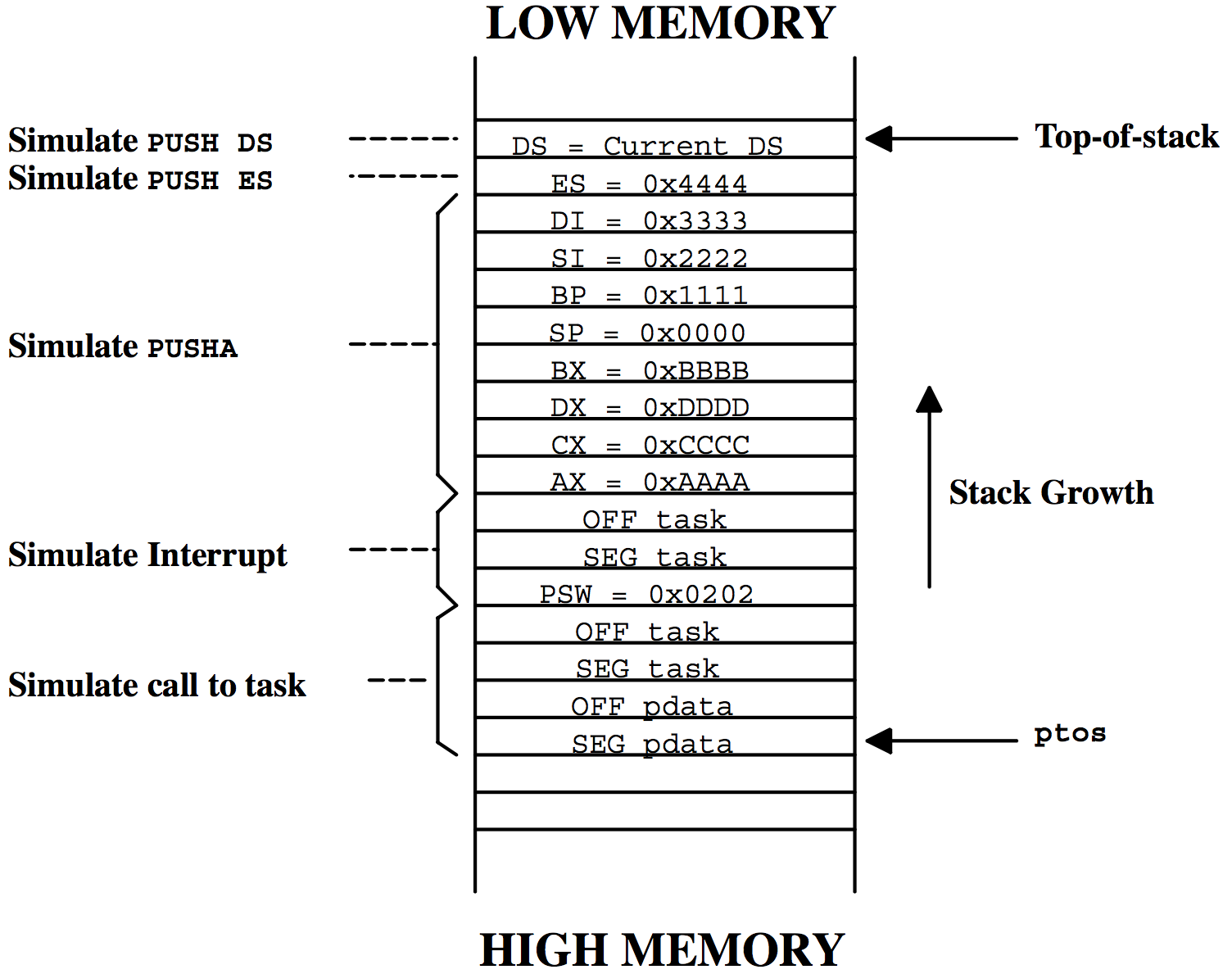
When you create a task, you pass the start address of the task ( task ), a pointer ( pdata ), the task’s top-of-stack ( ptos ), and the task’s priority (prio) to OSTaskCreate() or OSTaskCreateExt() . OSTaskCreateExt() requires additional arguments, but these are irrelevant in discussing OSTaskStkInit() . To properly initialize the stack frame, OSTaskStkInit() (Listing 14.3) requires only the first three arguments just mentioned (i.e., task , pdata , and ptos ).
OS_STK  *OSTaskStkInit (void  (*task)(void *pd),
                        void   *pdata,
                        OS_STK *ptos,
                        INT16U  opt)
{
    INT16U *stk;


    opt    = opt;
    stk    = (INT16U *)ptos;                            (1)
    *stk-- = (INT16U)FP_SEG(pdata);                     (2)
    *stk-- = (INT16U)FP_OFF(pdata);
    *stk-- = (INT16U)FP_SEG(task);                      (3)
    *stk-- = (INT16U)FP_OFF(task);
    *stk-- = (INT16U)0x0202;                            (4)
    *stk-- = (INT16U)FP_SEG(task);
    *stk-- = (INT16U)FP_OFF(task);
    *stk-- = (INT16U)0xAAAA;                            (5)
    *stk-- = (INT16U)0xCCCC;
    *stk-- = (INT16U)0xDDDD;
    *stk-- = (INT16U)0xBBBB;
    *stk-- = (INT16U)0x0000;
    *stk-- = (INT16U)0x1111;
    *stk-- = (INT16U)0x2222;
    *stk-- = (INT16U)0x3333;
    *stk-- = (INT16U)0x4444;
    *stk   = _DS;                                        (6)
    return ((OS_STK *)stk);                              (7)
}
(1) OSTaskStkInit() creates and initializes a local pointer to 16-bit elements because stack entries are 16 bits wide on the 80x86. Note that µC/OS-II requires that the pointer ptos points to an empty stack entry.
(2) The Borland C compiler passes the argument pdata on the stack instead of registers. Because of this, pdata is placed on the stack frame with the offset and segment in the order shown.
(3) The address of your task is placed on the stack next. In theory, this should be the return address of your task. However, in µC/OS-II, a task must never return, so what is placed here is not really critical.
(4) The status word (SW) along with the task address are placed on the stack to simulate the behavior of the processor in response to an interrupt. The SW register is initialized to 0x0202. This allows the task to have interrupts enabled when it starts. You can in fact start all your tasks with interrupts disabled by forcing SW to 0x0002 instead. There are no options in µC/OS-II to selectively enable interrupts upon startup for some tasks and disable interrupts upon task startup for others. In other words, either all tasks have interrupts disabled upon startup or all tasks have them disabled. You could, however, overcome this limitation by passing the desired interrupt startup state of a task by using pdata or the opt argument for task created with OSTaskCreateExt(). However, the latter is not currently implemented. If you chose to have interrupts disabled, each task needs to enable them when they execute. In this case, you also have to modify the code for OS_TaskIdle() and OS_TaskStat() to enable interrupts in those functions. If you don’t, your application will crash! I would thus recommend that you leave SW initialized to 0x0202 and have interrupts enabled when the task starts.
(5) The remaining registers are placed on the stack to simulate the PUSHA, PUSH ES, and PUSH DS instructions, which are assumed to be found at the beginning of every ISR. Note that the AX, BX, CX, DX, SP, BP, SI, and DI registers are placed to satisfy the order of the PUSHA instruction. If you port this code to a ‘plain’ 8086 processor, you may want to simulate the PUSHA instruction or place the registers in a neater order. You should also note that each register has a unique value instead of all zeros. This can be useful for debugging.
(6) Also, the Borland compiler supports “pseudoregisters” (i.e., the _DS keyword notifies the compiler to obtain the value of the DS register), which in this case is used to copy the current value of the DS register to the simulated stack frame.
(7) Once completed, OSTaskStkInit() returns the address of the new top-of-stack. OSTaskCreate() or OSTaskCreateExt() takes this address and saves it in the task’s OS_TCB.
OSTaskStkInit_FPE_x86()
When floating-point emulation is enable (see the Borland documentation), the stack of the Borland compiled program is organized as shown in Figure 14.3. The compiler assumes that the application runs in a single threaded (i.e., tasking) environment.
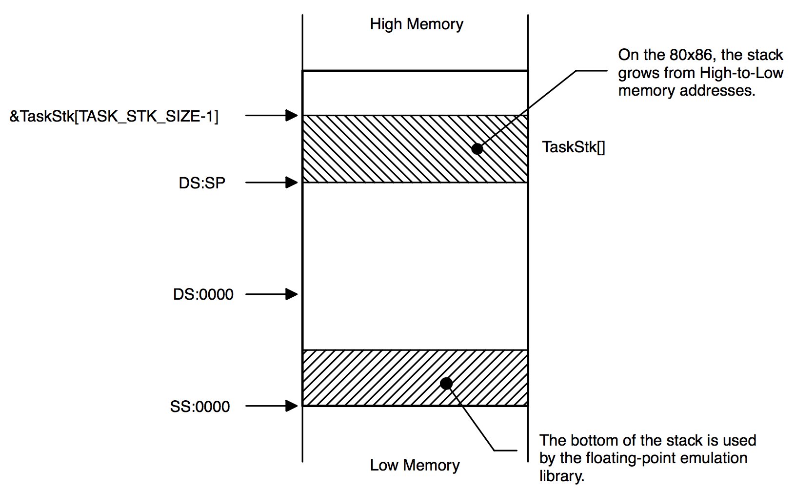
The Borland C Floating-Point Emulation (FPE) library assumes that about 300 bytes starting at SS:0x0000 are reserved to hold floating-point emulation variables. As far as I can tell, this applies to the ‘large memory model’ only. To accommodate this, a special function ( OSTaskStkInit_FPE_x86() ) must be called prior to calling either OSTaskCreate() or OSTaskCreateExt() to properly initialize the stack frame of each task that needs to perform floating-point operations. This function applies to Borland V3.x and V4.5x compilers and thus, OSTaskStkInit_FPE_x86() would most likely not be included in a port using a different compiler.
The floating-point emulation library stores its data within the reserved space in relation to the current SS register value, assuming that some space starting form SS up (from SS:0x0000 up) is reserved for floating point operations.
µCOS-II’s task stacks are generally allocated statically as shown below.
OS_STK Task1Stk[TASK_STK_SIZE]; /* stack table for task 1 */
OS_TSK Task2Stk[TASK_STK_SIZE]; /* stack table for task 2 */
When a task is created by µCOS-II the highest table address of the stack is pass to OSTaskCreate() (or OSTaskCreateExt()) as shown below:
OSTaskCreate(Task1, (void*)0, &Task1Stk[TASK_STK_SIZE-1], prio1);
OSTaskCreate(Task2, (void*)0, &Task2Stk[TASK_STK_SIZE-1], prio2);
The stack of Task1() starts at DS:&Task1Stk[TASK_STK_SIZE-1] while the stack of Task2() starts at DS:&Task2Stk[TASK_STK_SIZE-1]. Once initialized by µC/OS-II, the tasks top-of-stack (TOS) is saved in the task’s OS_TCB (Task Control Block).
The stack of the two tasks created from the previous code is shown in Figure 14.5. As can be seen, both tasks are part of the same segment and, more importantly, they share the same segment base since both stacks are allocated from the same data segment. When µC/OS-II loads a task during a context switch, it sets the SS register to the value of the DS register of the stack. This causes a problem since both tasks would have to share the same floating-point emulation variables!
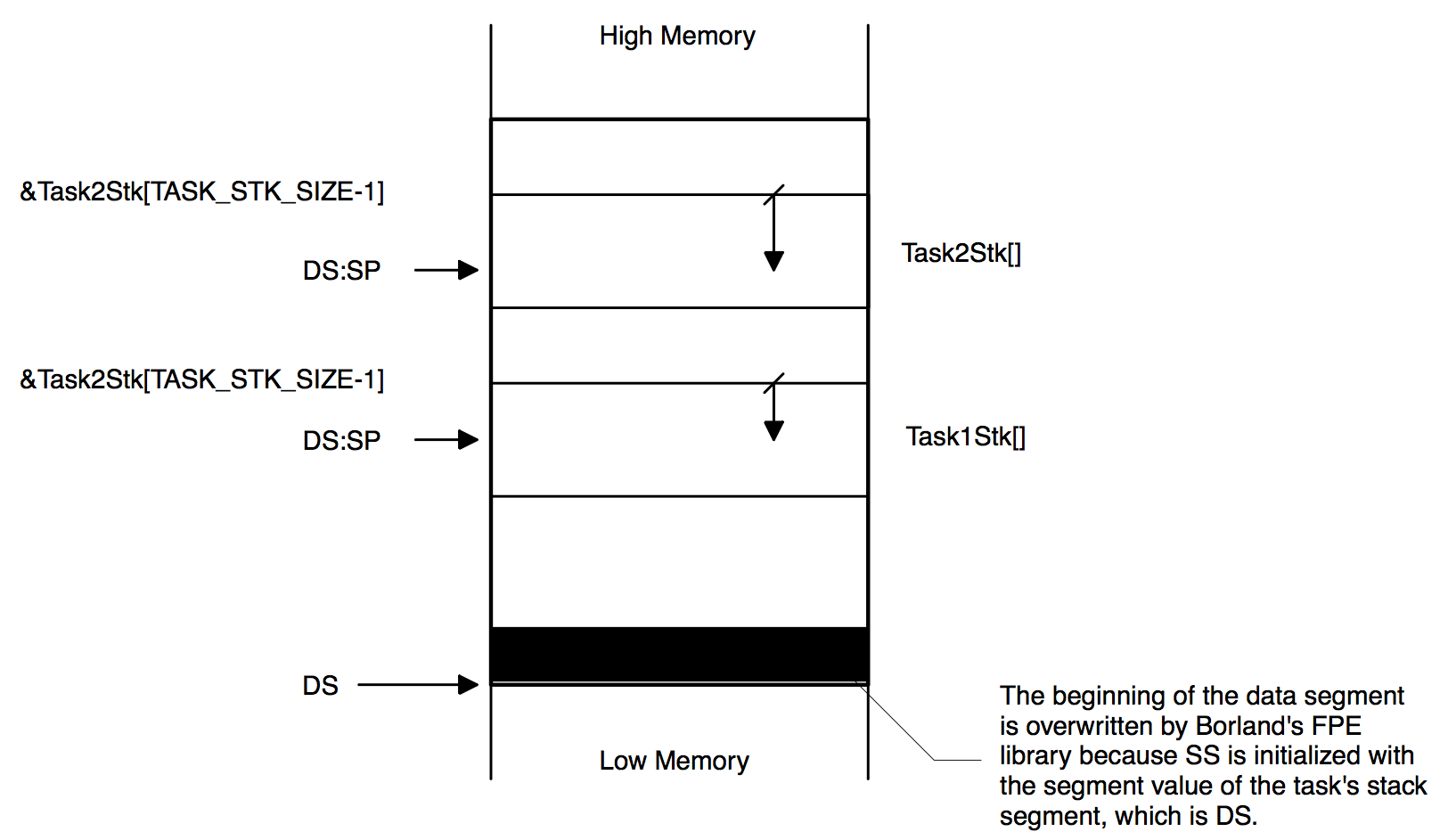
The beginning of the data segment is overwritten with the floating-point emulation library even when we use a semaphore. Protecting this resource with a semaphore would allow exclusive access to the floating-point variables but it does not protect the data segment from being overwriting. Even a single µCOS-II task using floating point overwrites the data segment! Further system behavior depends on what data are overwritten and typically data segment overwriting crashes the system.
A similar situation occurs when the stacks are allocated from the heap since we don’t know what part of memory is being overwritten. Typically, the heap is corrupted because the floating-point emulation library overwrites the header of the heap allocated block.
To fix this problem, the function OSTaskStkInit_FPE_x86() shown in Listing 14.4 needs to be called prior to creating a task. This function basically ‘normalizes’ the stack so that every stack starts at SS:0x0000 and, the function reserves and properly initializes the floating-point emulation variables for the task being created.
void  OSTaskStkInit_FPE_x86 (OS_STK **pptos,
                             OS_STK **ppbos,
                             INT32U  *psize)
{
    INT32U   lin_tos;
    INT32U   lin_bos;
    INT16U   seg;
    INT16U   off;
    INT32U   bytes;

    seg      = FP_SEG(*pptos);                           (1)
    off      = FP_OFF(*pptos);
    lin_tos  = ((INT32U)seg <<; 4) + (INT32U)off;        (2)
    bytes    = *psize * sizeof(OS_STK);                  (3)
    lin_bos  = (lin_tos - bytes + 15) & 0xFFFFFFF0L;     (4)

    seg      = (INT16U)(lin_bos >> 4);                   (5)
    *ppbos   = (OS_STK *)MK_FP(seg, 0x0000);             (6)
    memcpy(*ppbos, MK_FP(_SS, 0), 384);                  (7)
    bytes    = bytes - 16;                               (8)
    *pptos   = (OS_STK *)MK_FP(seg, (INT16U)bytes);      (9)
    *ppbos   = (OS_STK *)MK_FP(seg, 384);               (10)
    bytes    = bytes - 384;                             (11)
    *psize   = bytes / sizeof(OS_STK);                  (12)
}
(1) OSTaskStkInit_FPE_x86() starts off by decomposing the TOS into its segment and offset components.
(2) We then convert the address of the TOS into a linear address. Remember that on the 80x86 (Real Mode), the segment is multiplied by 16 and added to the offset to form the actual memory address.
(3) We then determine the size of the stack (in number of bytes). Remember that with µC/OS-II, you must declare a stack using the OS_STK data type which may represent an 8-bit wide stack, a 16-bit wide stack or a 32-bit wide stack. For the Borland compiler, the stack width is 16 bits but it’s always better to use the C operator sizeof().
(4) The linear address for the BOS is then determined by subtracting the number of bytes allocated to the stack from the TOS address. You should note that I added 15 bytes to the bottom of the stack and ANDed it with 0xFFFFFFF0L so that I would align the BOS on a ‘paragraph’ boundary (i.e., a 16-byte boundary).
(5) From the BOS’s linear address, we determine the new segment of the BOS.
(6) A far pointer with an offset of 0x0000 is then created and assigned to the new BOS pointer.
(7) To initialize the floating-point emulation variables of the task’s stack, we can simply copy the bottom of the calling’s task stack into the new stack. You should note that the calling task MUST have also been created from a task that has it’s stack initialized with the floating-point emulation variables. Failure to do this could cause unpredictable results. The Borland Floating-Point Emulation (FPE) assumes that about 300 bytes starting at SS:0x0000 are reserved to hold floating-point emulation variables. This applies to the ‘large memory model’ only. Note that I decided to copy 384 bytes (0x0180). It turns out that you don’t need to copy this many bytes but I find it safe to add a little extra in case of expansion. This also means that your task stack MUST have at least 384 bytes PLUS the anticipated stack requirements of your task (including ISR nesting, of course). Note that _SS is a Borland ‘pseudoregister’ which allows the code to obtain the current value of the CPU’s stack segment register. Also, I decided to use the ANSI function memcpy() because the Borland most likely optimized this function.
(8) The next step to to determine the normalize address of the TOS. We first need to subtract 16 bytes because we aligned the stack on a page boundary. If I could guaranty that you would always align your stacks to a paragraph boundary, I would not have to do this.
(9) The new TOS is determined by making a far pointer using the new segment (found in L14.4(6)) and the new size of the stack (aligned to a paragraph).
(10) The final step is to move the BOS up by 384 bytes in case the BOS is used to perform stack checking (i.e., if your application calls OSTaskStkChk()).
(11)
(12) If you use stack checking, µC/OS-II needs to know the size of the new stack. Of course, we don’t want to start the stack check from the bottom of the original stack but in fact, the new stack.
As can be seen from the code, you need to pass three arguments to OSTaskStkInit_FPE_x86():
pptos
is a pointer to the task’s top-of-stack (TOS) pointer (a pointer to a pointer). The task’s TOS is passed to OSTaskCreate() or OSTaskCreateExt() when you create a task. The stack is allocated from the data space and consist of a value for the DS register and an offset from this segment register. Because OSTaskStkInit_FPE_x86() normalizes the TOS, a pointer to the initial TOS is passed to this function so that it can be altered.
ppbos
is a pointer to the task’s bottom-of-stack (BOS) pointer (a pointer to a pointer). The task’s BOS is not passed to OSTaskCreate() however, it is passed to OSTaskCreateExt(). In other words, ppbos is necessary for OSTaskCreateExt(). The bottom of this stack is generally not located at DS:0000 but instead, at some offset from the DS register. Because OSTaskStkInit_FPE_x86() normalizes the BOS, a pointer to the initial BOS is passed to this function so that it can be altered.
psize
is a pointer to a variable which contains the size of the stack.. The task’s size is not needed by OSTaskCreate() but it is for OSTaskCreateExt(). Because OSTaskStkInit_FPE_x86() reserves storage for the floating-point emulation variables, the available stack size is actually altered by this function which is why a pointer to the size is passed. You must ensure that you pass OSTaskStkInit_FPE_x86() a stack large enough to hold the floating-point emulation variables plus the anticipated stack space needed by your application task.
Figure 14.6 shows what OSTaskStkInit_FPE_x86() does. Note that paragraph alignment is not shown in Figure 14.6.
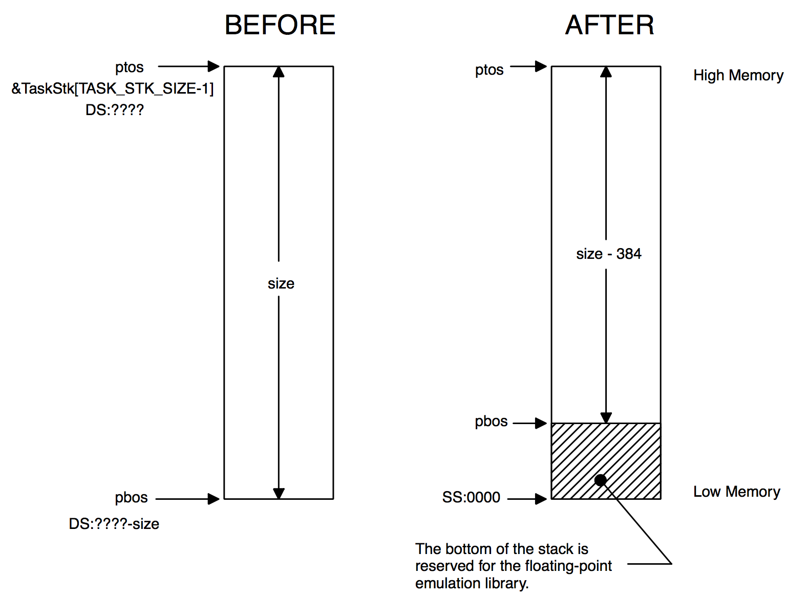
You would use OSTaskStkInit_FPE_x86() as shown in Listing 14.5 which contains an example with both OSTaskCreate() and OSTaskCreateExt() . The code shows that if your task is to do floating-point math, OSTaskStkInit_FPE_x86() MUST be called BEFORE calling either OSTaskCreate() or OSTaskCreateExt() in order to initialize the task's stack as just described. The returned pointers (ptos and pbos) MUST be used in the task creation call. Note that pbos would be passed to OSTaskCreateExt() as the new bottom of stack. You should note that if you were call OSTaskStkChk() (only if the task is created with OSTaskCreateExt() ) to determine the size of the task’s stack at run-time, then OSTaskStkChk() would report that the stack contains 384 bytes less than it’s original size (see the AFTER case of Figure 14.6)!
OS_STK Task1Stk[1000];
OS_STK Task2Stk[1000];


void main (void)
{
    OS_STK *ptos;
    OS_STK *pbos;
    INT32U  size;


    OSInit();
       .
       .
    ptos  = &Task1Stk[999];
    pbos  = &Task1Stk[0];
    size  = 1000;
    <b>OSTaskStkInit_FPE_x86(&ptos, &pbos, &size);</b>
    OSTaskCreate(Task1,
                 (void *)0,
                 ptos,
                 10);
       .
       .
    ptos  = &Task2Stk[999];
    pbos  = &Task2Stk[0];
    size  = 1000;
    <b>OSTaskStkInit_FPE_x86(&ptos, &pbos, &size)</b>;
    OSTaskCreateExt(Task2,
                    (void *)0,
                    ptos,
                    11,
                    11,
                    pbos,
                    size,
                    (void *)0,
                    OS_TASK_OPT_SAVE_FP);
       .
       .
    OSStart();
}
You should be careful that your code doesn’t generate any floating-point exception (e.g., divide by zero) because the floating-point library would not work properly under these circumstances. Run-time exceptions can, however, be avoided by adding range testing code.
OSTaskCreateHook()
As previously mentioned, OS_CPU_C.C does not define code for this function. In other words, no additional work is done by the port when a task is created. The assignment of ptcb to ptcb is done so that the compiler doesn’t complain about OSTaskCreateHook() not doing anything with the argument.
void  OSTaskCreateHook (OS_TCB *ptcb)
{
    ptcb = ptcb;
}
OSTaskDelHook()
As previously mentioned, OS_CPU_C.C does not define code for this function. In other words, no additional work is done by the port when a task is deleted. The assignment of ptcb to ptcb is again done so that the compiler doesn’t complain about OSTaskDelHook() not doing anything with the argument.
void  OSTaskDelHook (OS_TCB *ptcb)
{
    ptcb = ptcb;
}
OSTaskSwHook()
Again, OS_CPU_C.C doesn’t do anything in this function. You should note that I added the ‘skeleton’ of the code you would need if you were toactually do something in OSTaskSwHook().
void  OSTaskSwHook (void)
{
#if 0
    if (OSRunning == TRUE) {
        /* Save for task being 'switched-out' */
    }
    /* Code for task being 'switched-in'      */
#endif
}
OSTaskIdleHook()
Again, OS_CPU_C.C doesn’t do anything in this function.
void  OSTaskIdleHook (void)
{
}
OSTaskStatHook()
OS_CPU_C.C doesn’t do anything in this function. See Example 3 in Chapter 1 for an example on what you can do with this function.
void  OSTaskStatHook (void)
{
}
OSTimeTickHook()
OS_CPU_C.C doesn’t do anything in this function either.
void  OSTimeTickHook (void)
{
}
OSInitHookBegin()
OS_CPU_C.C doesn’t do anything in this function.
void  OSInitHookBegin (void)
{
}
OSInitHookEnd()
OS_CPU_C.C doesn’t do anything in this function.
void  OSInitHookEnd (void)
{
}
OSTCBInitHook()
OS_CPU_C.C doesn’t do anything in this function.
void  OSTCBInitHook (void)
{
}
OS_CPU_A.ASM
A µC/OS-II port requires that you write four assembly language functions:
OSStartHighRdy()
OSCtxSw()
OSIntCtxSw()
OSTickISR()
OSStartHighRdy()
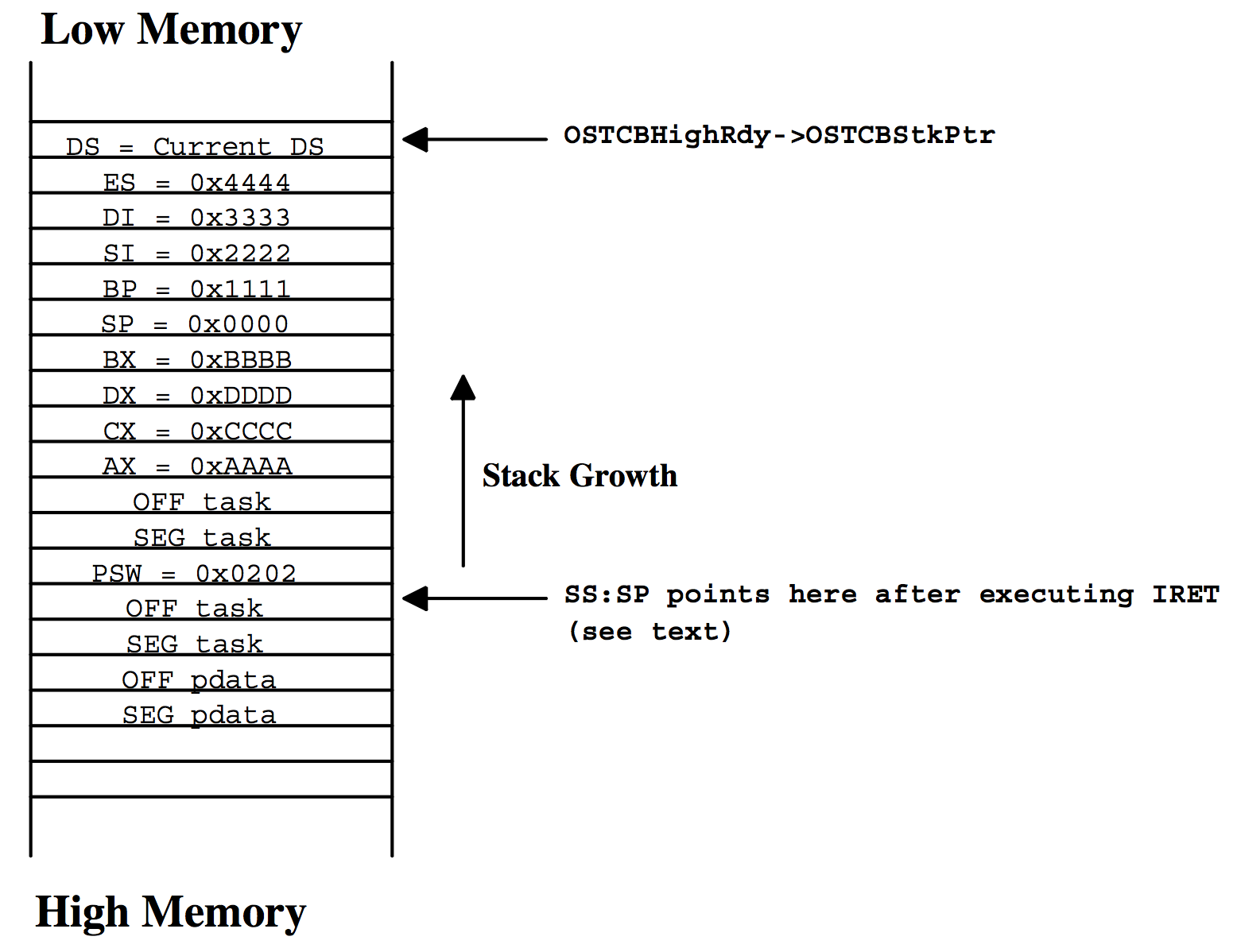
This function is called by OSStart() to start the highest priority task ready to run. However, before you can call OSStart(), you must have called OSInit() and then created at least one task [see OSTaskCreate() and OSTaskCreateExt()]. OSStart() sets up OSTCBHighRdy so that it points to the task control block of the task with the highest priority. Figure 14.7 shows the stack frame for an 80x86 real-mode task created by either OSTaskCreate() or OSTaskCreateExt() just before OSStart() calls OSStartHighRdy().
The code for OSStartHighRdy() is shown in Listing 14.15.
_OSStartHighRdy  PROC FAR

            MOV    AX, SEG _OSTCBHighRdy
            MOV    DS, AX
;
            CALL   FAR PTR _OSTaskSwHook                         (1)
;
            MOV    AL, 1                                         (2)
            MOV    BYTE PTR DS:_OSRunning, AL
;
            LES    BX, DWORD PTR DS:_OSTCBHighRdy                (3)
            MOV    SS, ES:[BX+2]
            MOV    SP, ES:[BX+0]
;
            POP    DS                                            (4)
            POP    ES
            POPA
;
            IRET                                                 (5)

_OSStartHighRdy  ENDP
(1) As mentioned in Chapter 13, OSStartHighRdy() must call OSTaskSwHook() when it starts. Remember that your OSTaskSwHook() function must check the state of OSRunning (which should be FALSE at this point) so that it only performs a restore context operation instead of a save and restore context.
(2) OSStartHighRdy() then sets OSRunning to TRUE so that subsequent calls to OSTaskSwHook() will be able to perform both save and restore operations. Because the code is done in assembly language, there is no way to get the exact value of TRUE from the C compiler. I’m thus assuming that TRUE is 1.
(3) OSStartHighRdy() then retrieves and loads the stack pointer from the task’s OS_TCB. As I mentionned before, I decided to store the stack pointer at the beginning of the task control block (i.e., its OS_TCB) to make it easier to access from assembly language.
(4) OSStartHighRdy() then restores the contents of all the CPU integer registers from the task’s stack.
(5) The IRET instruction is executed to perform a return from interrupt. Remember that the stack frame of the task was created so that it looks as if an interrupt occurred and all the CPU registers were pushed onto the task’s stack. The IRET instruction pulls the task address and places it into the CS:IP registers followed by the value to load into the SW register (called status word or flags).
As seen in Figure 14.7, upon executing the IRET instruction, the stack pointer (SS:SP) points to the return address of the task and ‘looks’ as if the task was called by a normal function. SS:SP+4 points to the argument pdata, which is passed to the task. In other words, your task will not know whether it was called by OSStartHighRdy() or any other function!
OSCtxSw()
A task-level context switch is accomplished on the 80x86 processor by executing a software interrupt instruction. The interrupt service routine must vector to OSCtxSw(). The sequence of events that leads µC/OS-II to vector to OSCtxSw() begins when the current task calls a service provided by µC/OS-II, which causes a higher priority task to be ready to run. At the end of the service call, µC/OS-II calls the function OS_Sched(), which concludes that the current task is no longer the most important task to run. OS_Sched() loads the address of the OS_TCB of the highest priority task into OSTCBHighRdy, then executes the software interrupt instruction by invoking the macro OS_TASK_SW(). Note that the variable OSTCBCur already contains a pointer to the current task’s task control block, OS_TCB. The code for OSCtxSw() is shown in Listing 14.16.
_OSCtxSw    PROC   FAR                                           (1)
;
            PUSHA                                                (2)
            PUSH   ES
            PUSH   DS
;
            MOV    AX, SEG _OSTCBCur
            MOV    DS, AX
;
            LES    BX, DWORD PTR DS:_OSTCBCur                    (3)
            MOV    ES:[BX+2], SS
            MOV    ES:[BX+0], SP
;
            CALL   FAR PTR _OSTaskSwHook                         (4)
;
            MOV    AX, WORD PTR DS:_OSTCBHighRdy+2               (5)
            MOV    DX, WORD PTR DS:_OSTCBHighRdy
            MOV    WORD PTR DS:_OSTCBCur+2, AX
            MOV    WORD PTR DS:_OSTCBCur, DX
;
            MOV    AL, BYTE PTR DS:_OSPrioHighRdy                (6)
            MOV    BYTE PTR DS:_OSPrioCur, AL
;
            LES    BX, DWORD PTR DS:_OSTCBHighRdy                (7)
            MOV    SS, ES:[BX+2]
            MOV    SP, ES:[BX]
;
            POP    DS                                            (8)
            POP    ES
            POPA
;
            IRET                                                 (9)
;
_OSCtxSw    ENDP
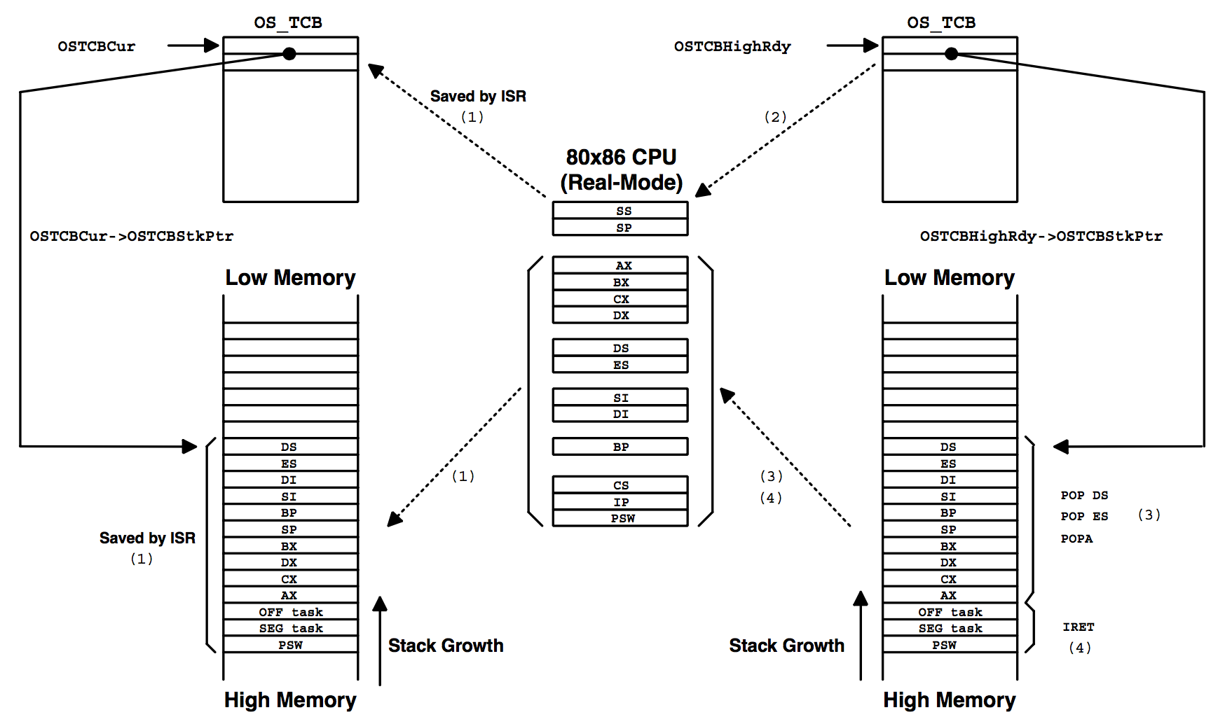
Figure 14.8 shows the stack frames of the task being suspended and the task being resumed.
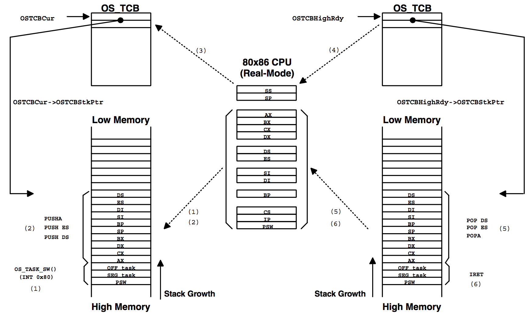
The notes below apply both and simultaneously to Listing 14.16 and Figure 14.8. When reading each numbered note, refer to both the listing and the figure.
(1) F14.8
(1) L14.16 - On the 80x86 processor, the software interrupt instruction forces the SW register to be pushed onto the current task’s stack followed by the return address (segment and then offset) of the task that executed the INT instruction [i.e., the task that invoked OS_TASK_SW()].
(2) F14.8
(2) L14.16 - The remaining CPU registers of the task to suspend are saved onto the current task’s stack.
(3) F14.8
(3) L14.16 - The pointer to the new stack frame is saved into the task’s OS_TCB. This pointer is composed of the stack segment (SS register) and the stack pointer (SS register). The OS_TCB in µC/OS-II is organized such that the stack pointer is placed at the beginning of the OS_TCB structure to make it easier to save and restore the stack pointer using assembly language.
(4) L14.16 - The user-definable task switch hook OSTaskSwHook() is then called. Note that when OSTaskSwHook() is called, OSTCBCur points to the current task’s OS_TCB, while OSTCBHighRdy points to the new task’s OS_TCB. You can thus access each task’s OS_TCB from OSTaskSwHook(). If you never intend to use the context switch hook, you can comment out the call and save yourself a few clock cycles during the context switch. In other words, there is no point in going through the overhead of calling and returning from a funtion if your port doesn’t use OSTaskSwHook(). As a general rule, however, I like to make the call to be consistent between port.
(5) L14.16 - Upon return from OSTaskSwHook(), OSTCBHighRdy is copied to OSTCBCur because the new task will now also be the current task.
(6) L14.16 - Also, OSPrioHighRdy is copied to OSPrioCur for the same reason.
(4) F14.8
(7) L14.16 - At this point, OSCtxSw() can load the processor’s registers with the new task’s context. This is done by retrieving the SS and SP registers from the new task’s OS_TCB.
(5) L14.16 - F14.8
(8) L14.16 - The remaining CPU registers are pulled from the new task’s stack.
(6) F14.8
(9) L14.16 - An IRET instruction is executed to load the new task’s program counter and status word. After this instruction, the processor resumes execution of the new task.
Note that interrupts are disabled during OSCtxSw() and also during execution of the user-definable function OSTaskSwHook().
OSIntCtxSw()
OSIntCtxSw() is called by OSIntExit() to perform a context switch from an ISR (Interrupt Service Routine). Because OSIntCtxSw() is called from an ISR, it is assumed that all the processor registers are already properly saved onto the interrupted task’s stack.
The code shown in Listing 14.17 is identical to OSCtxSw(), except for the fact that there is no need to save the registers (i.e., no PUSHA, PUSH ES, or PUSH DS) onto the stack because it is assumed that the beginning of the ISR has already done that. Also, it is also assumed that the stack pointer is saved into the task’s OS_TCB by the ISR. Figure 14.9 also shows the context switch process, from OSIntCtxSw()’ s point of view.
To understand the difference, let’s assume that the processor receives an interrupt. Let’s also supposed that interrupts are enabled. The processor completes the current instruction and initiates an interrupt handling procedure.
(1) The 80x86 automatically pushes the processor’s SW register followed by the return address of the interrupted task onto the stack. The CPU then vectors to the proper ISR. µC/OS-II requires that your ISR begins by saving the rest of the processor registers. Once the registers are saved, µC/OS-II requires that you also save the contents of the stack pointer in the task’s OS_TCB.
Your ISR then needs to either call OSIntEnter() or, increment the global variable OSIntNesting by one. At this point, we can assume that the task is suspended and we could, if needed, switch to a different task.
The ISR can now start servicing the interrupting device and possibly, make a higher priority task ready. This occurs if the ISR sends a message to a task by calling either OSFlagPost(), OSMboxPost(), OSMboxPostOpt(), OSQPostFront(), OSQPost() or OSQPostOpt(). A higher priority task can also be resumed if the ISR calls OSTaskResume(), OSTimeTick() or OSTimeDlyResume().
Assume that a higher priority task is made ready to run by the ISR. µC/OS-II requires that an ISR calls OSIntExit() when it has finished servicing the interrupting device. OSIntExit() basically tell µC/OS-II that it’s time to return back to task-level code if all nested interrupts have completed. In other words, when OSIntNesting is decremented to 0 by OSIntExit(), OSIntExit() would return to task level code.
When OSIntExit() executes, it notices that the interrupted task is no longer the task that needs to run because a higher priority task is now ready. In this case, the pointer OSTCBHighRdy is made to point to the new task’s OS_TCB, and OSIntExit() calls OSIntCtxSw() to perform the context switch.
_OSIntCtxSw PROC   FAR
;
            CALL   FAR PTR _OSTaskSwHook                        (1)
;
            MOV    AX, SEG _OSTCBCur
            MOV    DS, AX
;
            MOV    AX, WORD PTR DS:_OSTCBHighRdy+2              (2)
            MOV    DX, WORD PTR DS:_OSTCBHighRdy
            MOV    WORD PTR DS:_OSTCBCur+2, AX
            MOV    WORD PTR DS:_OSTCBCur, DX
;
            MOV    AL, BYTE PTR DS:_OSPrioHighRdy               (3)
            MOV    BYTE PTR DS:_OSPrioCur, AL
;
            LES    BX, DWORD PTR DS:_OSTCBHighRdy               (4)
            MOV    SS, ES:[BX+2]
            MOV    SP, ES:[BX]
;
            POP    DS                                           (5)
            POP    ES
            POPA
;
            IRET                                                (6)
;
_OSIntCtxSw ENDP
The notes below apply both and simultaneously to Listing 14.17 and Figure 14.7. When reading each numbered note, refer to both the listing and the figure.
(1) L14.17 - The first thing OSIntCtxSw() does is call the user-definable task switch hook OSTaskSwHook(). Note that when OSTaskSwHook() is called, OSTCBCur points to the current task’s OS_TCB, while OSTCBHighRdy points to the new task’s OS_TCB. You can thus access each task’s OS_TCB from OSTaskSwHook(). Again, if you never intend to use the context switch hook, you can comment out the call and save yourself a few clock cycles during the context switch.
(2) L14.17 - Upon return from OSTaskSwHook(), OSTCBHighRdy is copied to OSTCBCur because the new task will now also be the current task.
(3) L14.17 - OSPrioHighRdy is also copied to OSPrioCur for the same reason.
(2) F14.9
(4) L14.17 - At this point, OSCtxSw() can load the processor’s registers with the new task’s context. This is done by retrieving the SS and SP registers from the new task’s OS_TCB.
(3) F14.9
(5) L14.17 - The remaining CPU registers are pulled from the stack.
(4) F14.9
(6) L14.17 - An IRET instruction is executed to load the new task’s program counter and status word. After this instruction, the processor resumes execution of the new task.
Note that interrupts are disabled during OSIntCtxSw() and also during execution of the user-definable function OSTaskSwHook().
OSTickISR()
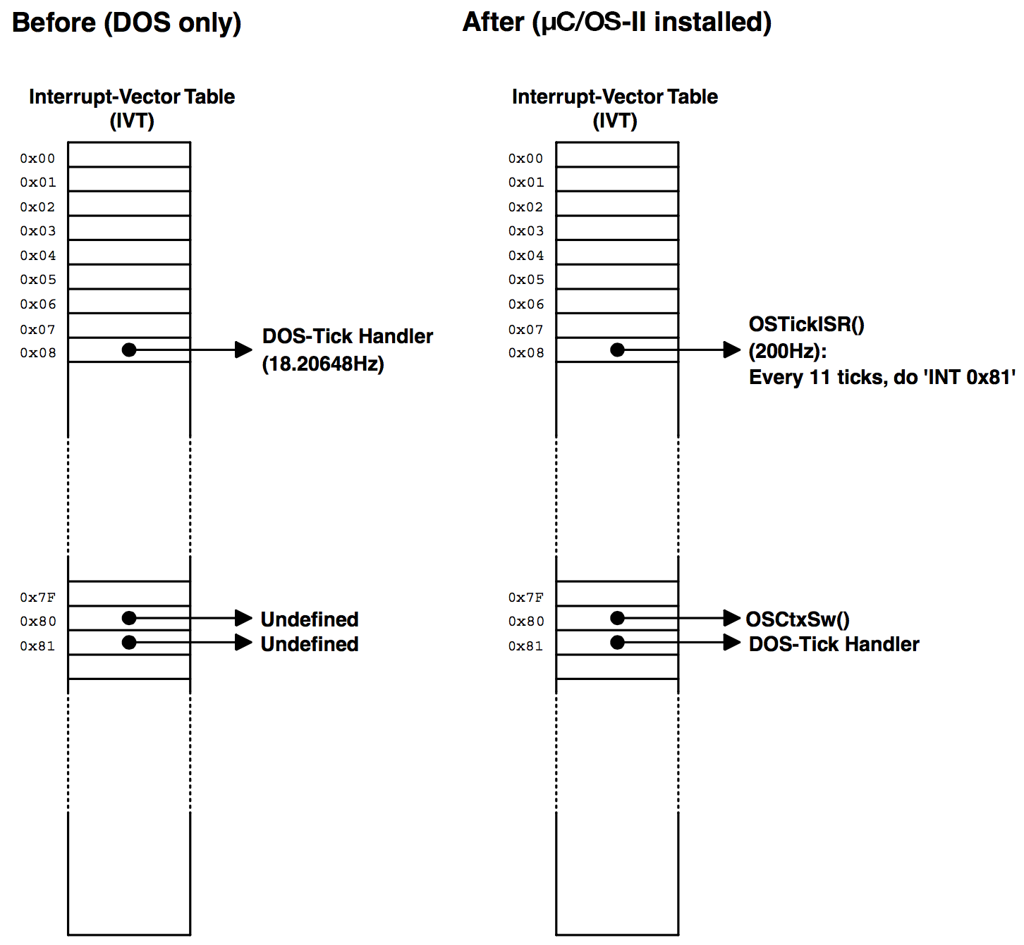
As mentioned in section 14.03.05, Tick Rate, the tick rate of an RTOS should be set between 10 and 100Hz. On the PC, the ticker occurs every 54.93ms (18.20648Hz) and is obtained by a hardware timer that interrupts the CPU. Recall that I reprogrammed the tick rate to 200Hz. The ticker on the PC is assigned to vector 0x08 but µC/OS-II redefined it so that it vectors to OSTickISR() instead. Because of this, the PC’s tick handler is saved [see PC.C, PC_DOSSaveReturn()] in vector 129 (0x81). To satisfy DOS, however, the PC’s handler is called every 54.93ms (described shortly). Figure 14.10 shows the contents of the interrupt vector table (IVT) before and after installing µC/OS-II.
With µC/OS-II, it is very important that you enable ticker interrupts after multitasking has started; that is, after calling OSStart() . In the case of the PC, however, ticker interrupts are already occurring before you actually execute your µC/OS-II application.
To prevent the ISR from invoking OSTickISR() until µC/OS-II is ready, do the following:
main():
Call OSInit() to initialize µC/OS-II.
Call PC_DOSSaveReturn() (see PC.C)
Call PC_VectSet() to install context switch vector OSCtxSw() at vector 0x80
Create at least one application task
Call OSStart() when you are ready to multitask
The first task to execute needs to:
Install OSTickISR() at vector 0x08
Change the tick rate from 18.20648 to 200Hz
The tick handler on the PC is somewhat tricky, so I will explain it using the pseudocode shown in Listing 14.18. This code would normally be written in assembly language.
void  OSTickISR (void)
{
    Save all registers on the current task's stack;                   (1)
    OSIntNesting++;                                                   (2)
    if (OSIntNesting == 1) {                                          (3)
        OSTCBCur->OSTCBStkPtr = SS:SP                                 (4)
    }
    OSTickDOSCtr--;                                                   (5)
    if (OSTickDOSCtr == 0) {                                          (6)
        OSTickDOSCtr = 11;                                            (7)
        INT 81H;     /* Interrupt will be cleared by DOS */
    } else {
        Send EOI to PIC;                                              (8)
    }
    OSTimeTick();                                                     (9)
    OSIntExit();                                                     (10)
    Restore all registers that were save on the current task's stack;(11)
    Return from Interrupt;                                           (12)
}
(1) Like all µC/OS-II ISRs, all registers need to be saved onto the current task’s stack.
(2) Upon entering an ISR, you need to tell µC/OS-II that you are starting an ISR by either calling OSIntEnter() or directly incrementing OSIntNesting. I like to increment OSIntNesting directly because it’s faster. However, OSIntEnter() checks that you don’t increment OSIntNesting beyond 255 and thus, is safer if you nest your ISRs.
(3)
(4) If this ISR is the first nested ISR, you need to save the stack pointer into the current task’s OS_TCB.
(5)
(6)
(7) Next, the counter OSTickDOSCtr is decremented and when it reaches 0, the DOS ticker handler is called. This happens every 54.93ms.
(8) Ten times out of 11, however, a command is sent to the Priority Interrupt Controller (PIC) to clear the interrupt. Note that there is no need to do this when the DOS ticker is called because the DOS tick handler directly clears the interrupt source.
(9) OSTickISR() then calls OSTimeTick() so that µC/OS-II can update all tasks waiting for time to expire or pending for some event to occur, with a timeout.
(10) At the completion of all ISRs, OSIntExit() is called. If a higher priority task has been made ready by this ISR (or any other nested ISRs) and this is the last nested ISR, then OSIntExit() will not return to OSTickISR()! Instead, OSIntCtxSw() restores the processor’s context of the new task and issues an IRET. If the ISR is not the last nested ISR or the ISR did not cause a higher priority task to be ready, then OSIntExit() returns back to OSTickISR().
(11)
(12) IF OSIntExit() returns, it’s because it didn’t find any higher priority task to run and thus, the contents of the interrupt task’s processor registers are restored. When the IRET instruction is executed, the ISR returns to the interrupted task.
The actual code for OSTickISR() is shown in Listing 14.19 for your reference. The number in Listing 14.19 corresponds to the same item in Listing 14.18. You should note that the actual code in the file contains comments.
_OSTickISR  PROC   FAR
;
            PUSHA                                               (1)
            PUSH   ES
            PUSH   DS
;
            MOV    AX, SEG(_OSIntNesting)                       (2)
            MOV    DS, AX
            INC    BYTE PTR DS:_OSIntNesting
;
            CMP    BYTE PTR DS:_OSIntNesting, 1                 (3)
            JNE    SHORT _OSTickISR1
            MOV    AX, SEG(_OSTCBCur)
            MOV    DS, AX
            LES    BX, DWORD PTR DS:_OSTCBCur                   (4)
            MOV    ES:[BX+2], SS
            MOV    ES:[BX+0], SP
;
_OSTickISR1:
            MOV    AX, SEG(_OSTickDOSCtr)                       (5)
            MOV    DS, AX
            DEC    BYTE PTR DS:_OSTickDOSCtr
            CMP    BYTE PTR DS:_OSTickDOSCtr, 0                 (6)
            JNE    SHORT _OSTickISR2
;
            MOV    BYTE PTR DS:_OSTickDOSCtr, 11                (7)
            INT    081H
            JMP    SHORT _OSTickISR3

_OSTickISR2:
            MOV    AL, 20H                                      (8)
            MOV    DX, 20H
            OUT    DX, AL
;
_OSTickISR3:
            CALL   FAR PTR _OSTimeTick                          (9)
;
            CALL   FAR PTR _OSIntExit                          (10)
;
            POP    DS                                          (11)
            POP    ES
            POPA
;
            IRET                                               (12)
;
_OSTickISR  ENDP
You can simplify OSTickISR() by not increasing the tick rate from 18.20648 to 200Hz, as shown in the pseudocode in Listing 14.20. The actual code is shown in Listing 14.21 and matches the same item from Listing 14.20. This code is included so that you can model your ISRs after it.
void OSTickISR (void)
{
    Save all registers on the current task's stack;                   (1)
    OSIntNesting++;                                                   (2)
    if (OSIntNesting == 1) {                                          (3)
        OSTCBCur->OSTCBStkPtr = SS:SP                                 (4)
    }
    INT 81H;                                                          (5)
    OSTimeTick();                                                     (6)
    OSIntExit();                                                      (7)
    Restore all registers that were save on the current task's stack; (8)
    Return from Interrupt;                                            (9)
}
(1) Like all µC/OS-II ISRs, all registers need to be saved onto the current task’s stack.
(2) Upon entering an ISR, you need to tell µC/OS-II that you are starting an ISR by either calling OSIntEnter() or directly incrementing OSIntNesting. I like to increment OSIntNesting directly because it’s faster.
(3)
(4) If this ISR is the first nested ISR, you need to save the stack pointer into the current task’s OS_TCB.
(5) Next, the DOS tick handler is called by issuing an INT caal (see the remapping of the IVT, Figure 14.10). Note that you do not need to clear the interrupt because this is handled by the DOS ticker.
(6) Call OSTimeTick() so that µC/OS-II can update all tasks waiting for time to expire or pending on some event to occur with a timeout. If your ISR is not for the DOS tick, this is the place you would put the code to service your own interrupt.
(7) When you are done servicing the ISR, call OSIntExit(). If the ISR makes a higher priority task ready to run, OSIntExit() will not return to this ISR but instead, context switch to the new, higher priority task.
(8) The processor registers are restored.
(9) The ISR returns to the interrupted source by executing an IRET instruction.
Note that you must not change the tick rate by calling PC_SetTickRate() if you are to use this version of the code. In other words, you must leave the tick rate alone. You also have to change the configuration constant OS_TICKS_PER_SEC (see OS_CFG.H) from 200 to 18. You should note that the tick rate is not actually 18 but 18.20648. You need to be aware of this, especially if you want to delay a task for 10 seconds. You would specify 10 *OS_TICKS_PER_SEC ticks and it would actually end up being only 9.8866 seconds!
_OSTickISR  PROC   FAR
;
            PUSHA                                             (1)
            PUSH   ES
            PUSH   DS
;
            MOV    AX, SEG(_OSIntNesting)                     (2)
            MOV    DS, AX
            INC    BYTE PTR DS:_OSIntNesting
;
            CMP    BYTE PTR DS:_OSIntNesting, 1               (3)
            JNE    SHORT _OSTickISR1
            MOV    AX, SEG(_OSTCBCur)
            MOV    DS, AX
            LES    BX, DWORD PTR DS:_OSTCBCur                 (4)
            MOV    ES:[BX+2], SS
            MOV    ES:[BX+0], SP
;
_OSTickISR1:
            INT    081H                                       (5)
;
            CALL   FAR PTR _OSTimeTick                        (6)
;
            CALL   FAR PTR _OSIntExit                         (7)
;
            POP    DS                                         (8)
            POP    ES
            POPA
;
            IRET                                              (9)
;
_OSTickISR  ENDP
Memory Usage
Table 14.3 shows the amount of memory (both code and data space) used by µC/OS-II based on the value of configuration constants. Data in this case means RAM and code means ROM if µC/OS-II is used in an embedded system.
The spreadsheet is actually provided in the downloadable package (uCOS-II-RAM-Calc.XLS). You need Microsoft Excel for Office 2000 (or higher) to use this file. The spreadsheet allows you to do “what-if” scenarios based on the options you select. You can change the configuration values (in RED) and see how they affects µC/OS-II’s ROM and RAM usage on the 80x86. For the ???_EN values, you MUST use either 0 or 1.
I setup the Borland compiler to generate the fastest code. The number of bytes shown are not meant to be accurate but are simply provided to give you a relative idea of how much code space each of the µC/OS-II group of services require. For example, if you don’t need message queue services (OS_Q_EN is set to 0), then you will save between 1,900 and 2,200 bytes of code space.
The spreadsheet also shows you the difference in code size based on the value of OS_ARG_CHK_EN in your OS_CFG.H. You don’t need to change the value of OS_ARG_CHK_EN to see the difference.
The Data column is not as straightforward. Notice that the stacks for both the idle task and the statistics task have been set to 1,024 bytes (1Kb) each. Based on your own requirements, these number may be higher or lower. As a minimum, µC/OS-II requires about 3,500 bytes of RAM for µC/OS-II internal data structures if you configure the maximum number of tasks (62 application tasks).
Table 14.4 shows how µC/OS-II can scale down the amount of memory required with most of the services disabled. In this case, I allowed only 16 tasks with 20 priority levels (0 to 19). Notice that the Code space is now between 2,400 and 2,700 bytes and Data space for µC/OS-II internals is only about 500 bytes. However, just about the only service you can use in your tasks is OSTimeDly()!
If you use an 80x86 processor, you will most likely not be too restricted with memory and thus, µC/OS-II will most likely not be the largest user of memory.
µCOS-II, The Real-Time Kernel V2.5280x86, Real Mode, Large Model | ||||||
|---|---|---|---|---|---|---|
| Configuration Parameters | Value in OS_CFG.H | Data (Bytes) | Code (Bytes) OS_ARG_CHK_EN == 0 | Code (Bytes) OS_ARG_CHK_EN == 1 | Delta Code (Bytes) | Delta Code (%) |
| TOTAL | 5523 | 13048 | 14919 | 1871 | 14% | |
OS_MAX_EVENTS | 10 | 164 | ||||
OS_MAX_FLAGS | 2 | 14 | ||||
OS_MAX_MEM_PART | 2 | 44 | ||||
OS_MAX_QS | 2 | 52 | ||||
OS_MAX_TASKS | 62 | 2,880 | ||||
OS_LOWEST_PRIO | 63 | 264 | ||||
OS_TASK_lDLE_STK_SIZE | 512 | 1024 | ||||
OS_TASK_STAT_EN | 1 | 10 | 351 | 351 | ||
OS_TASK_STAT_STK_SIZE | 512 | 1024 | ||||
OS_ARG_CHK_EN | 1 | |||||
OS_CPU_HO0KS_EN | 1 | |||||
| MINIMUM | 2177 | 2493 | 316 | |||
OS_FLAG_EN | 1 | 2174 | 2539 | 82 | ||
OS_FLAG_WAIT_CLR_EN | 1 | 108 | ||||
OS_FLAG_ACCEPT_EN | 1 | 41 | ||||
OS_FLAG_DEL_EN | 1 | 95 | ||||
OS_FLAG_OUERY_EN | 1 | 39 | ||||
OS_MBOX_EN | 1 | 958 | 1185 | 55 | ||
OS_MBOX_ACCEPT_EN | 1 | 23 | ||||
OS_MBOX_DEL_EN | 1 | 49 | ||||
OS_MBOX_POST_EN | 1 | 35 | ||||
OS_MBOX_POST_OPT_EN | 1 | 39 | ||||
OS_MBOX_QUERY_EN | 1 | 25 | ||||
OS_MEM_EN | 1 | 689 | 838 | 123 | ||
OS_MEM_QUERY_EN | 1 | 26 | ||||
OS_MUTEX_EN | 1 | 1596 | 1792 | 83 | ||
OS_MUTEX_ACCEPT_EN | 1 | 39 | ||||
OS_MUTEX_DEL_EN | 1 | 47 | ||||
OS_MUTEX_OUERY_EN | 1 | 27 | ||||
OS_O_EN | 1 | 1917 | 2206 | 45 | ||
OS_Q_ACCEPT_EN | 1 | 23 | ||||
OS_O_DEL_EN | 1 | 49 | ||||
OS_Q_FLUSH_EN | 1 | 25 | ||||
OS_Q_POST_EN | 1 | 40 | ||||
OS_Q_POST_FRONT_EN | 1 | 40 | ||||
OS_Q_POST_OPT_EN | 1 | 40 | ||||
OS_O_OUERY_EN | 1 | 27 | ||||
OS_SEM_EN | 1 | 707 | 864 | 62 | ||
OS_SEM_ACCEPT_EN | 1 | 21 | ||||
OS_SEM_DEL_EN | 1 | 49 | ||||
OS_SEM_QUERY_EN | 1 | 25 | ||||
OS_TASK_CHANGE_PRI0_EN | 1 | 444 | 455 | 22 | ||
OS_TASK_CREATE_EN | 1 | 185 | 196 | 11 | ||
OS_TASK_CREATE_EXT_EN | 1 | 441 | 467 | 26 | ||
OS_TASK_DEL_EN | 1 | 527 | 578 | 51 | ||
OS_TASK_SUSPEND_EN | 1 | 264 | 300 | 36 | ||
OS_TASK_OUERY_EN | 1 | 87 | 103 | 16 | ||
OS_TIME_DLY_HMSM_EN | 1 | 248 | 248 | |||
OS_TIME_DLY_RESUME_EN | 1 | 122 | 132 | 10 | ||
OS_TIME_GET_SET_EN | 1 | 59 | 59 | |||
OS_SCHED_LOCK_EN | 1 | 102 | 102 | |||
| µC/OS-II Internals | 47 | |||||
| Total Application Stacks | 0 | |||||
| Total Application RAM | 0 | |||||
µCOS-II, The Real-Time Kernel V2.5280x86, Real Mode, Large Model | ||||||
|---|---|---|---|---|---|---|
| Configuration Parameters | Value in OS_CFG.H | Data (Bytes) | Code (Bytes) OS_ARG_CHK_EN == 0 | Code (Bytes) OS_ARG_CHK_EN == 1 | Delta Code (Bytes) | Delta Code (%) |
| TOTAL | 1508 | 2362 | 2689 | 327 | 14% | |
OS_MAX_EVENTS | 10 | |||||
OS_MAX_FLAGS | 2 | |||||
OS_MAX_MEM_PART | 2 | |||||
OS_MAX_QS | 2 | |||||
OS_MAX_TASKS | 16 | 360 | ||||
OS_LOWEST_PRI0 | 20 | 87 | ||||
OS_TASK_lDLE_STK_SIZE | 512 | 1024 | ||||
OS_TASK_STAT_EN | 0 | |||||
OS_TASK_STAT_STK_SIZE | 512 | |||||
OS_ARG_CHK_EN | 1 | |||||
OS_CPU_HO0KS_EN | 1 | |||||
| MINIMUM | 2177 | 2493 | 316 | |||
OS_FLAG_EN | 0 | |||||
OS_FLAG_WAIT_CLR_EN | 1 | |||||
OS_FLAG_ACCEPT_EN | 1 | |||||
OS_FLAG_DEL_EN | 1 | |||||
OS_FLAG_OUERY_EN | 1 | |||||
OS_MBOX_EN | 1 | |||||
OS_MBOX_ACCEPT_EN | 1 | |||||
OS_MBOX_DEL_EN | 1 | |||||
OS_MBOX_POST_EN | 1 | |||||
OS_MBOX_POST_OPT_EN | 1 | |||||
OS_MBOX_QUERY_EN | 1 | |||||
OS_MEM_EN | 0 | |||||
OS_MEM_QUERY_EN | 1 | |||||
OS_MUTEX_EN | 0 | |||||
OS_MUTEX_ACCEPT_EN | 1 | |||||
OS_MUTEX_DEL_EN | 1 | |||||
OS_MUTEX_OUERY_EN | 1 | |||||
OS_Q_EN | 0 | |||||
OS_Q_ACCEPT_EN | 1 | |||||
OS_O_DEL_EN | 1 | |||||
OS_Q_FLUSH_EN | 1 | |||||
OS_Q_POST_EN | 1 | |||||
OS_Q_POST_FRONT_EN | 1 | |||||
OS_Q_POST_OPT_EN | 1 | |||||
OS_O_OUERY_EN | 1 | |||||
OS_SEM_EN | 0 | |||||
OS_SEM_ACCEPT_EN | 1 | |||||
OS_SEM_DEL_EN | 1 | |||||
OS_SEM_QUERY_EN | 1 | |||||
OS_TASK_CHANGE_PRIO_EN | 0 | |||||
OS_TASK_CREATE_EN | 1 | 185 | 196 | 11 | ||
OS_TASK_CREATE_EXT_EN | 0 | |||||
OS_TASK_DEL_EN | 0 | |||||
OS_TASK_SUSPEND_EN | 0 | |||||
OS_TASK_OUERY_EN | 0 | |||||
OS_TIME_DLY_HMSM_EN | 0 | |||||
OS_TIME_DLY_RESUME_EN | 0 | |||||
OS_TIME_GET_SET_EN | 0 | |||||
OS_SCHED_LOCK_EN | 0 | |||||
| µC/OS-II Internals | 37 | |||||
| Total Application Stacks | 0 | |||||
| Total Application RAM | 0 | |||||