Real-Time Systems Concepts
- Former user (Deleted)
- WES Admin
- Former user (Deleted)
Real-time systems are characterized by the severe consequences that result if logical as well as timing correctness properties of the system are not met. There are two types of real-time systems: SOFT and HARD. In a SOFT real-time system, tasks are performed by the system as fast as possible, but the tasks don’t have to finish by specific times. In HARD real-time systems, tasks have to be performed not only correctly but on time. Most real-time systems have a combination of SOFT and HARD requirements. Real-time applications cover a wide range, but most real-time systems are embedded. This means that the computer is built into a system and is not seen by the user as being a computer. The following list shows a few examples of embedded systems.
Process Control Food processing Automotive Engine controls Office Automation FAX machines Computer Peripherals Printers | Communication Switches Robots Aerospace Flight management systems Domestic Microwave ovens |
Real-time software applications are typically more difficult to design than non-real-time applications. This chapter describes real-time concepts.
Foreground/Background Systems
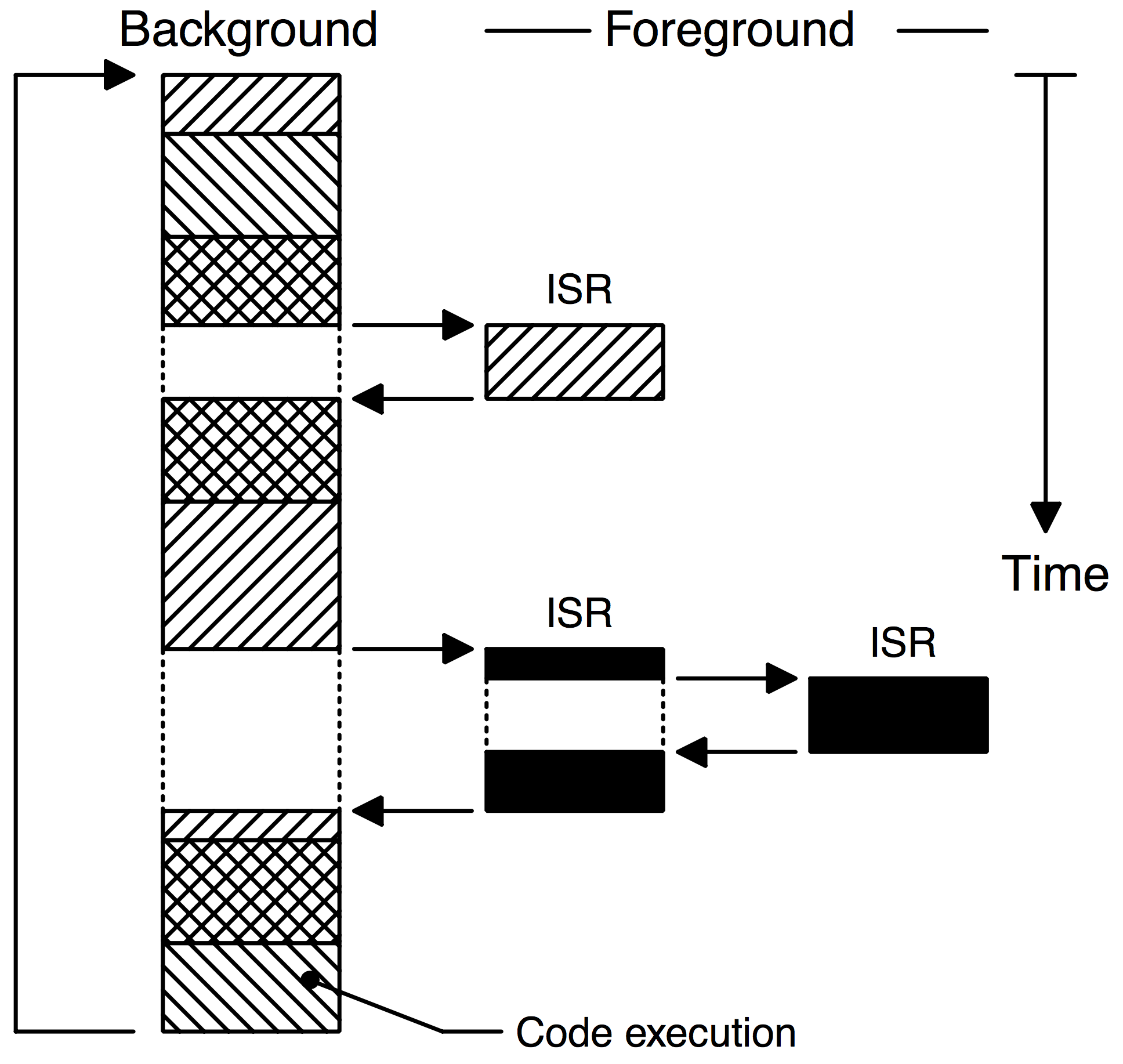
Small systems of low complexity are generally designed as shown in Figure 2.1. These systems are called foreground/background or super-loops. An application consists of an infinite loop that calls modules (i.e., functions) to perform the desired operations (background). Interrupt Service Routines (ISRs) handle asynchronous events (foreground). Foreground is also called interrupt level; background is called task level. Critical operations must be performed by the ISRs to ensure that they are dealt with in a timely fashion. Because of this, ISRs have a tendency to take longer than they should. Also, information for a background module made available by an ISR is not processed until the background routine gets its turn to execute. This is called the task level response. The worst case task-level response time depends on how long the background loop takes to execute. Because the execution time of typical code is not constant, the time for sµCcessive passes through a portion of the loop is non-deterministic. Furthermore, if a code change is made, the timing of the loop is affected.
Most high-volume microcontroller-based applications (e.g., microwave ovens, telephones, toys, and so on) are designed as foreground/background systems. Also, in microcontroller-based applications, it may be better (from a power consumption point of view) to halt the processor and perform all of the processing in ISRs. However, you can also halt the processor when µC/OS-II does not have any tasks to execute.
Critical Section of Code
A critical section of code, also called a critical region, is code that needs to be treated indivisibly. Once the section of code starts executing, it must not be interrupted. To ensure this, interrupts are typically disabled before the critical code is executed and enabled when the critical code is finished (see also section 2.03, Shared Resource).
Resource
A resource is any entity used by a task. A resource can thus be an I/O device, such as a printer, a keyboard, or a display, or a variable, a structure, or an array.
Shared Resource
A shared resource is a resource that can be used by more than one task. Each task should gain exclusive access to the shared resource to prevent data corruption. This is called mutual exclusion, and techniques to ensure mutual exclusion are discussed in section 2.18, Mutual Exclusion.
Multitasking
Multitasking is the process of scheduling and switching the CPU (Central Processing Unit) between several tasks; a single CPU switches its attention between several sequential tasks. Multitasking is like foreground/background with multiple backgrounds. Multitasking maximizes the utilization of the CPU and also provides for modular construction of applications. One of the most important aspects of multitasking is that it allows the application programmer to manage complexity inherent in real-time applications. Application programs are typically easier to design and maintain if multitasking is used.
Task
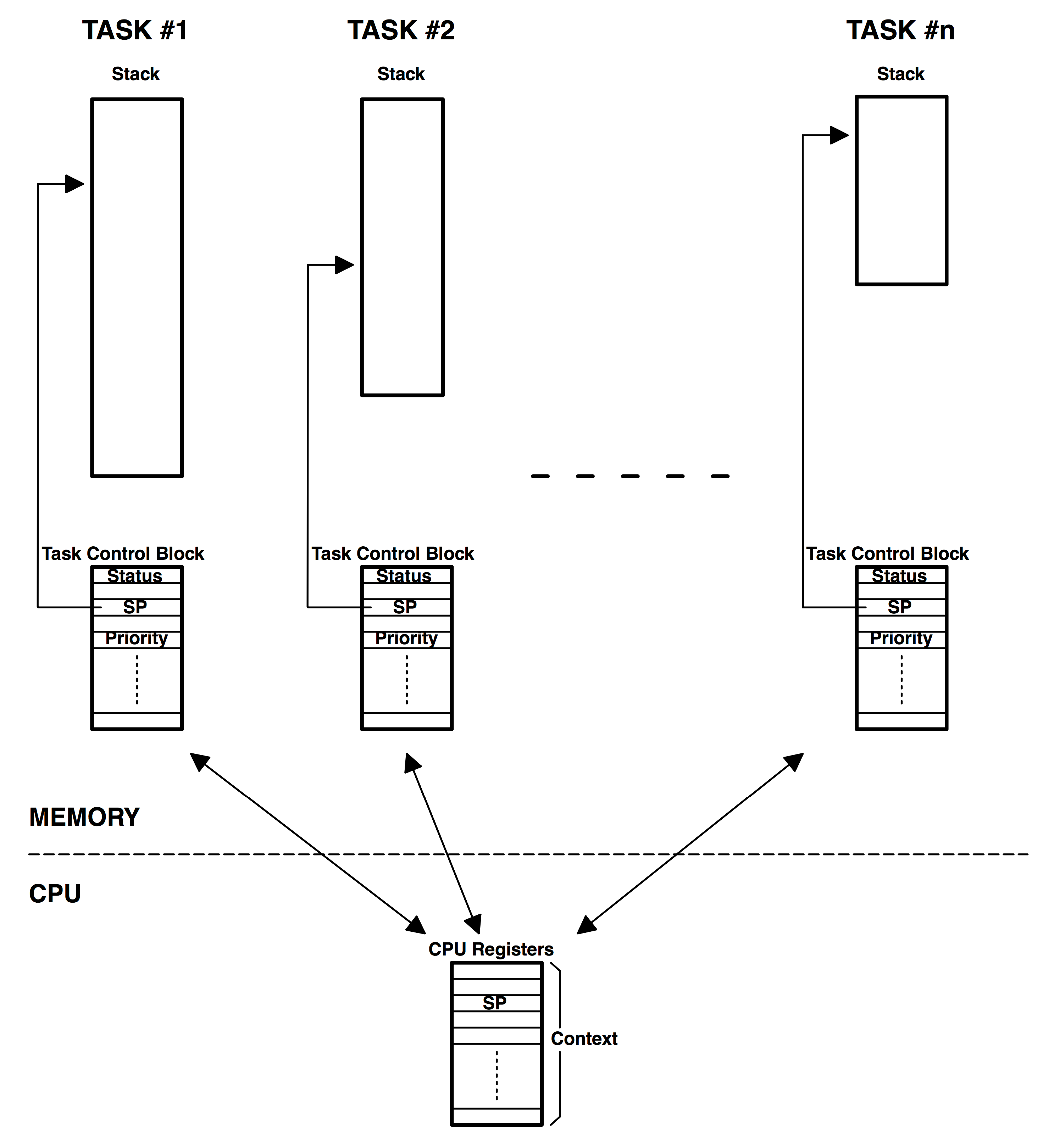
A task, also called a thread, is a simple program that thinks it has the CPU all to itself. The design process for a real-time application involves splitting the work to be done into tasks responsible for a portion of the problem. Each task is assigned a priority, its own set of CPU registers, and its own stack area (as shown in Figure 2.2).
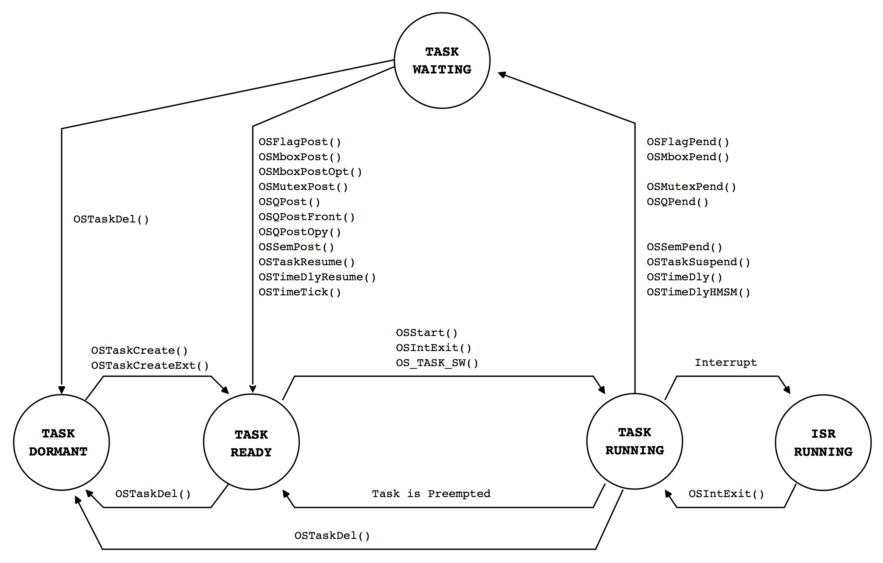
Each task typically is an infinite loop that can be in any one of five states: DORMANT, READY, RUNNING, WAITING (for an event), or ISR (interrupted) (Figure 2.3). The DORMANT state corresponds to a task that resides in memory but has not been made available to the multitasking kernel. A task is READY when it can execute but its priority is less than the currently running task. A task is RUNNING when it has control of the CPU. A task is WAITING when it requires the occurrence of an event (waiting for an I/O operation to complete, a shared resource to be available, a timing pulse to occur, time to expire, etc.). Finally, a task is in the ISR state when an interrupt has occurred and the CPU is in the process of servicing the interrupt. Figure 2.3 also shows the functions provided by µC/OS-II to make a task move from one state to another.
Context Switch (or Task Switch)
When a multitasking kernel decides to run a different task, it simply saves the current task’s context (CPU registers) in the current task’s context storage area — its stack (Figure 2.2). Once this operation is performed, the new task’s context is restored from its storage area then resumes execution of the new task’s code. This process is called a context switch or a task switch. Context switching adds overhead to the application. The more registers a CPU has, the higher the overhead. The time required to perform a context switch is determined by how many registers have to be saved and restored by the CPU. Performance of a real-time kernel should not be judged by how many context switches the kernel is capable of doing per second.
Kernel
The kernel is the part of a multitasking system responsible for the management of tasks (i.e., for managing the CPU’s time) and communication between tasks. The fundamental service provided by the kernel is context switching. The use of a real-time kernel generally simplifies the design of systems by allowing the application to be divided into multiple tasks managed by the kernel.
A kernel adds overhead to your system because the services provided by the kernel require execution time. The amount of overhead depends on how often you invoke these services. In a well designed application, a kernel will use up between 2 and 5% of CPU time. Because a kernel is software that gets added to your application, it requires extra ROM (code space) and additional RAM for the kernel data structures and, each task requires its own stack space, which has a tendency to eat up RAM quickly.
Single-chip microcontrollers are generally not able to run a real-time kernel because they have very little RAM. A kernel allows you to make better use of your CPU by providing you with indispensable services such as semaphore management, mailboxes, queues, time delays, etc. Once you design a system using a real-time kernel, you will not want to go back to a foreground/background system.
Scheduler
The scheduler, also called the dispatcher, is the part of the kernel responsible for determining which task will run next. Most real-time kernels are priority based. Each task is assigned a priority based on its importance. The priority for each task is application specific. In a priority-based kernel, control of the CPU is always given to the highest priority task ready to run. When the highest priority task gets the CPU, however, is determined by the type of kernel used. There are two types of priority-based kernels: non-preemptive and preemptive.
Non-Preemptive Kernel
Non-preemptive kernels require that each task does something to explicitly give up control of the CPU. To maintain the illusion of concurrency, this process must be done frequently. Non-preemptive scheduling is also called cooperative multitasking; tasks cooperate with each other to share the CPU. Asynchronous events are still handled by ISRs. An ISR can make a higher priority task ready to run, but the ISR always returns to the interrupted task. The new higher priority task will gain control of the CPU only when the current task gives up the CPU.
One of the advantages of a non-preemptive kernel is that interrupt latency is typically low (see the later discussion on interrupts). At the task level, non-preemptive kernels can also use non-reentrant functions (discussed later). Non-reentrant functions can be used by each task without fear of corruption by another task. This is because each task can run to completion before it relinquishes the CPU. However, non-reentrant functions should not be allowed to give up control of the CPU.
Task-level response using a non-preemptive kernel can be much lower than with foreground/background systems because task-level response is now given by the time of the longest task.
Another advantage of non-preemptive kernels is the lesser need to guard shared data through the use of semaphores. Each task owns the CPU, and you don’t have to fear that a task will be preempted. This is not an absolute rule, and in some instances, semaphores should still be used. Shared I/O devices may still require the use of mutual exclusion semaphores; for example, a task might still need exclusive access to a printer.
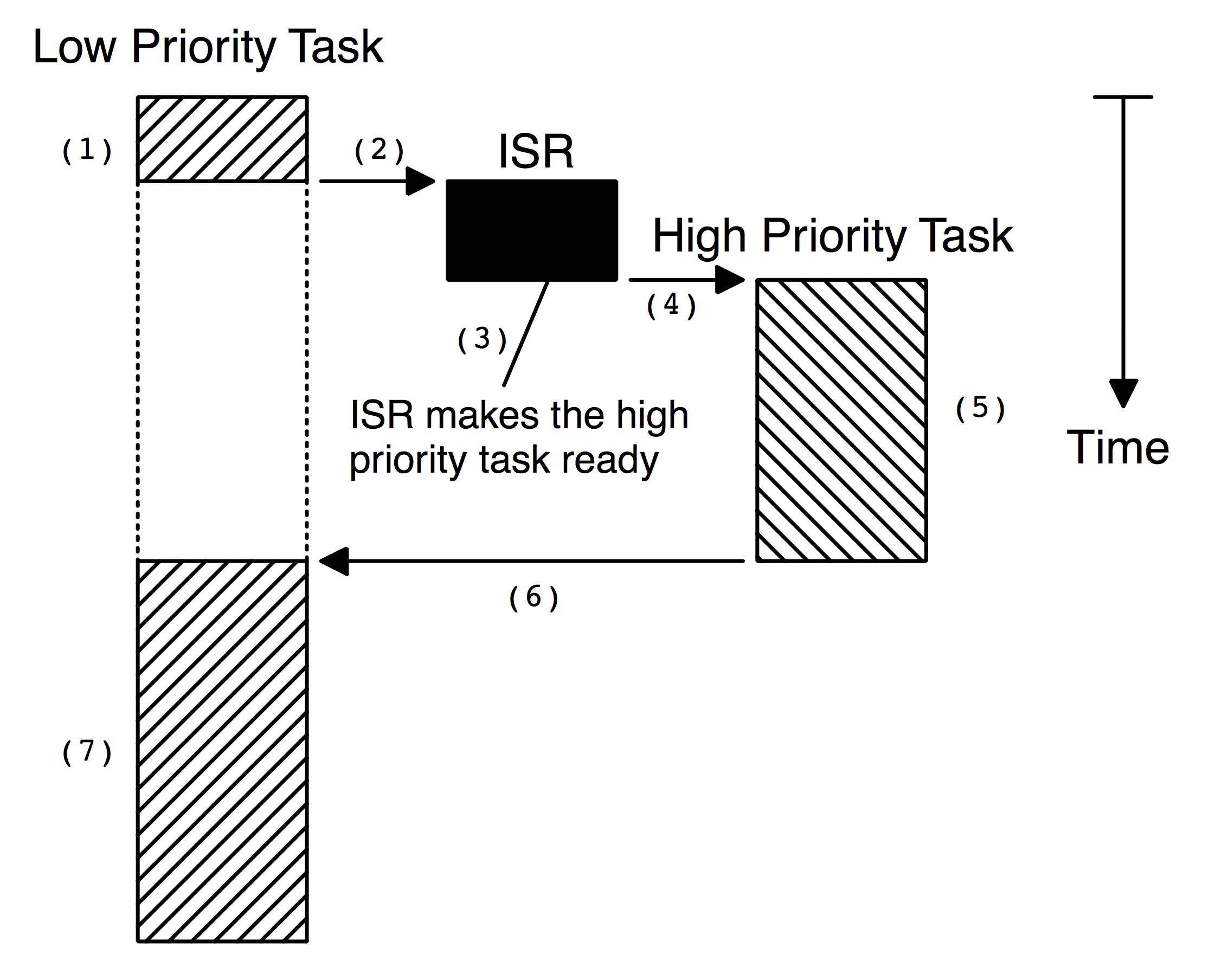
The execution profile of a non-preemptive kernel is shown in Figure 2.4 and described below.
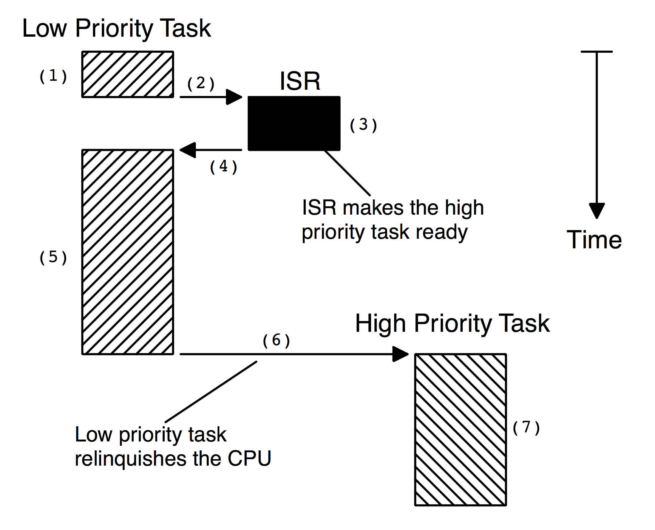
(1) A task is executing but gets interrupted.
(2) If interrupts are enabled, the CPU vectors (jumps) to the ISR.
(3) The ISR handles the event F2.4(3) and makes a higher priority task ready to run.
(4) Upon completion of the ISR, a Return From Interrupt instruction is executed, and the CPU returns to the interrupted task.
(5) The task code resumes at the instruction following the interrupted instruction.
(6) When the task code completes, it calls a service provided by the kernel to relinquish the CPU to another task.
(7) The kernel sees that a higher priority task has been made ready-to-run (it doesn’t necessarily knows that it was from an ISR nor does it care) and thus, the kernel performs a context switch so that it can run (i.e. execute) the higher priority task to handle the event signaled by the ISR.
The most important drawback of a non-preemptive kernel is responsiveness. A higher priority task that has been made ready to run may have to wait a long time to run because the current task must give up the CPU when it is ready to do so. As with background execution in foreground/background systems, task-level response time in a non-preemptive kernel is non-deterministic; you never really know when the highest priority task will get control of the CPU. It is up to your application to relinquish control of the CPU.
To summarize, a non-preemptive kernel allows each task to run until it voluntarily gives up control of the CPU. An interrupt preempts a task. Upon completion of the ISR, the ISR returns to the interrupted task. Task-level response is much better than with a foreground/background system but is still non-deterministic. Very few commercial kernels are non-preemptive.
Preemptive Kernel
A preemptive kernel is used when system responsiveness is important. Because of this, µC/OS-II and most commercial real-time kernels are preemptive. The highest priority task ready to run is always given control of the CPU. When a task makes a higher priority task ready to run, the current task is preempted (suspended) and the higher priority task is immediately given control of the CPU. If an ISR makes a higher priority task ready, when the ISR completes, the interrupted task is suspended and the new higher priority task is resumed.
The execution profile of a preemptive kernel is shown in Figure 2.5 and described below.
(1) A task is executing but gets interrupted.
(2) If interrupts are enabled, the CPU vectors (jumps) to the ISR.
(3) The ISR handles the event and makes a higher priority task ready to run. Upon completion of the ISR, a service provided by the kernel is invoked (i.e. a function provided by the kernel is called).
(4) & (5) This function knows that a more important task has been made ready-to-run and thus, instead of returning back to the interrupted task, the kernel will perform a context switch and execute the code of the more important task. When the more important task is done, another function provided by the kernel is called to put the task to sleep waiting for the event (i.e. the ISR) to occur.
(6) & (7) The kernel then ‘sees’ that a lower priority task needs to execute and another context switch is done to resume execution of the interrupted task.
With a preemptive kernel, execution of the highest priority task is deterministic; you can determine when it will get control of the CPU. Task-level response time is thus minimized by using a preemptive kernel.
Application code using a preemptive kernel should not use non-reentrant functions, unless exclusive access to these functions is ensured through the use of mutual exclusion semaphores, because both a low- and a high-priority task can use a common function. Corruption of data may occur if the higher priority task preempts a lower priority task that is using the function.
To summarize, a preemptive kernel always executes the highest priority task that is ready to run. An interrupt preempts a task. Upon completion of an ISR, the kernel resumes execution to the highest priority task ready to run (not the interrupted task). Task-level response is optimum and deterministic. µC/OS-II is a preemptive kernel.
Reentrancy
A reentrant function can be used by more than one task without fear of data corruption. A reentrant function can be interrupted at any time and resumed at a later time without loss of data. Reentrant functions either use local variables (i.e., CPU registers or variables on the stack) or protect data when global variables are used. An example of a reentrant function is shown in Listing 2.1.
void strcpy(char *dest, char *src)
{
    while (*dest++ = *src++) {
        ;
    }
    *dest = NUL;
}
Because copies of the arguments to strcpy() are placed on the task’s stack, strcpy() can be invoked by multiple tasks without fear that the tasks will corrupt each other’s pointers.
An example of a non-reentrant function is shown in Listing 2.2. swap() is a simple function that swaps the contents of its two arguments. For the sake of discussion, I assume that you are using a preemptive kernel, that interrupts are enabled, and that Temp is declared as a global integer:
int Temp;

void swap(int *x, int *y)
{
    Temp = *x;
    *x   = *y;
    *y   = Temp;
}
The programmer intended to make swap() usable by any task. Figure 2.6 shows what could happen if a low-priority task is interrupted while swap() is executing:
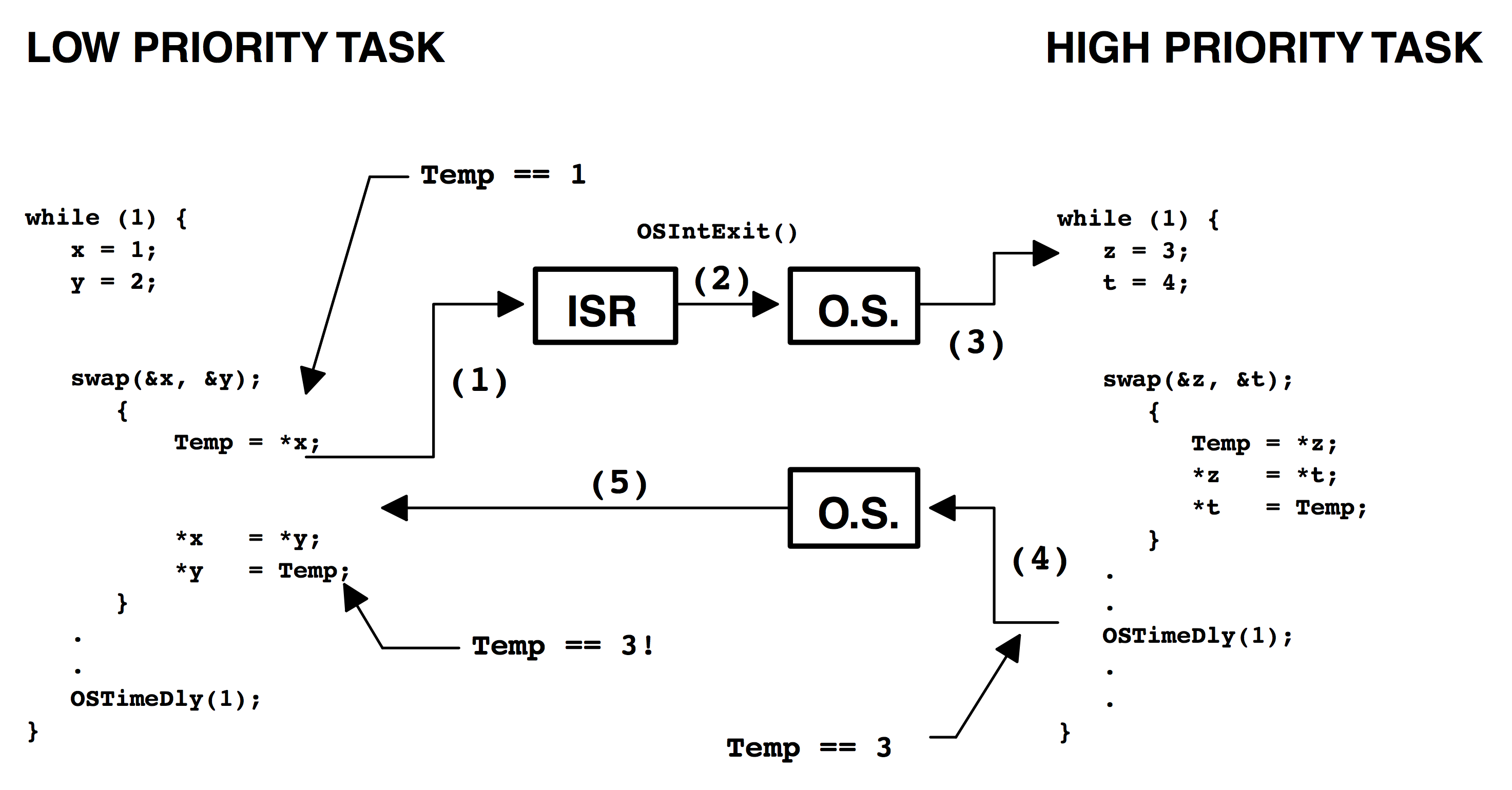
(1) When swap() is interrupted Temp contains 1.
(2) & (3) The ISR makes the higher priority task ready-to-run, so at the completion of the ISR, the kernel (assuming µC/OS-II) is invoked to switch to this task. The high-priority task sets Temp to 3 and swaps the contents of its variables correctly (i.e., z is 4 and t is 3).
(4) The high-priority task eventually relinquishes control to the low-priority task by calling a kernel service to delay itself for one clock tick (described later).
(5) The lower priority task is thus resumed. Note that at this point, Temp is still set to 3! When the low-priority task resumes execution, it sets y to 3 instead of 1.
Note that this a simple example, so it is obvious how to make the code reentrant. You can make swap() reentrant with one of the following techniques:
- Declare Temp local to
swap(). - Disable interrupts before the operation and enable them afterwards.
- Use a semaphore (described later).
- Other situations are not as easy to solve. An error caused by a non-reentrant function may not show up in your application during the testing phase; it will most likely occur once the product has been delivered! If you are new to multitasking, you will need to be careful when using non-reentrant functions.
If the interrupt occurs either before or after swap(), the x and y values for both tasks will be correct.
Round-Robin Scheduling
When two or more tasks have the same priority, the kernel allows one task to run for a predetermined amount of time, called a quantum, then selects another task. This is also called time slicing. The kernel gives control to the next task in line if
- the current task has no work to do during its time slice or
- the current task completes before the end of its time slice or
- the time slice ends.
µC/OS-II does not currently support round-robin scheduling. Each task must have a unique priority in your application.
Task Priority
A priority is assigned to each task. The more important the task, the higher the priority given to it. With most kernels, you are generally responsible for deciding what priority each task gets.
Static Priorities
Task priorities are said to be static when the priority of each task does not change during the application’s execution. Each task is thus given a fixed priority at compile time. All the tasks and their timing constraints are known at compile time in a system where priorities are static.
Dynamic Priorities
Task priorities are said to be dynamic if the priority of tasks can be changed during the application’s execution; each task can change its priority at run time. This is a desirable feature to have in a real-time kernel to avoid priority inversions.
Priority Inversions
Priority inversion is a problem in real-time systems and occurs mostly when you use a real-time kernel. Figure 2.7 illustrates a priority inversion scenario. Task 1 has a higher priority than Task 2, which in turn has a higher priority than Task 3.
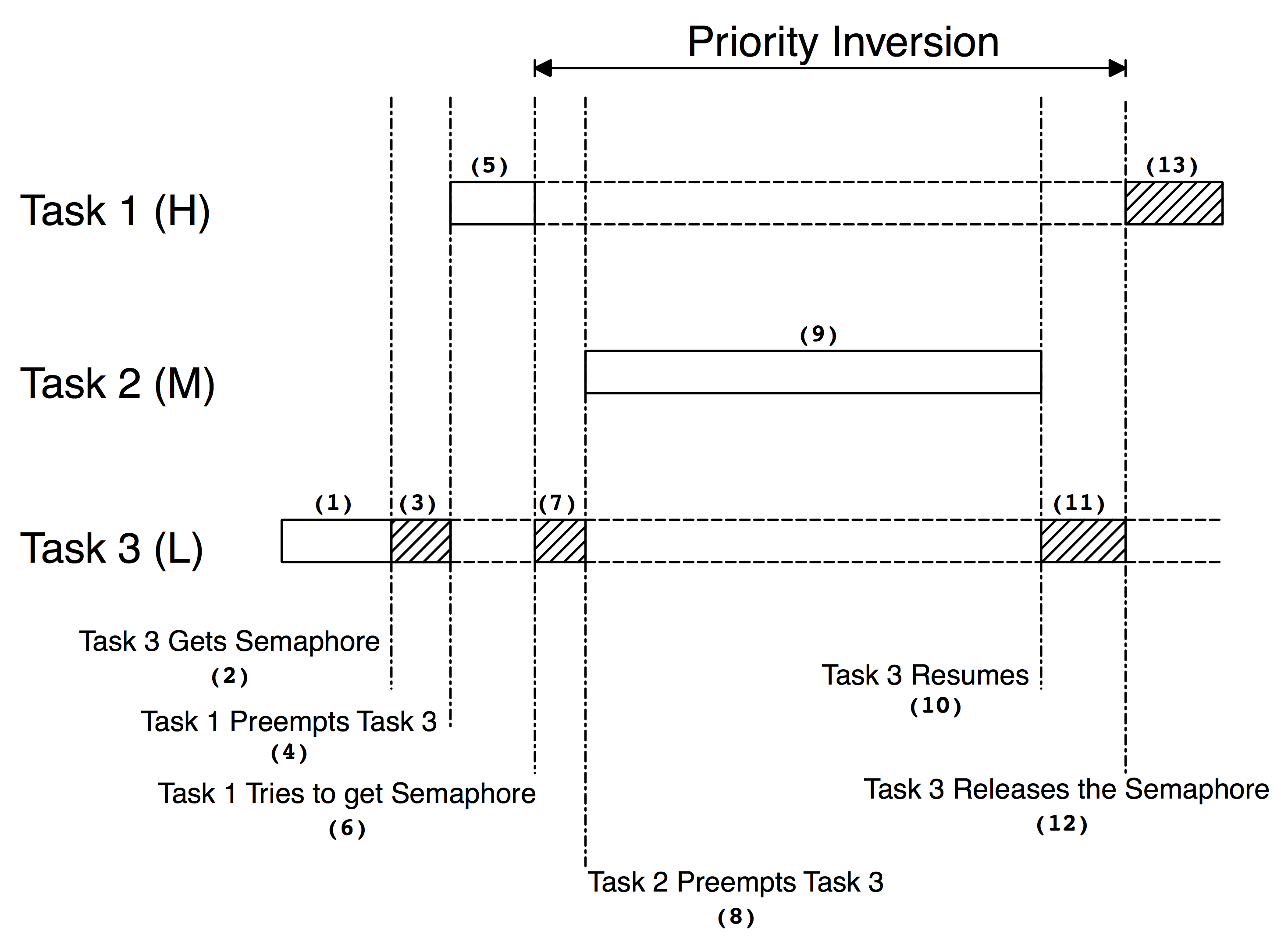
(1) Task 1 and Task 2 are both waiting for an event to occur and Task 3 is executing.
(2) At some point, Task 3 acquires a semaphore (see section 2.18.04, Semaphores), which it needs before it can access a shared resource.
(3) Task 3 performs some operations on the acquired resource.
(4) The event that Task 1 was waiting for occurs and thus, the kernel suspends Task 3 and start executing Task 1 because Task 1 has a higher priority.
(5)
(6) Task 1 executes for a while until it also wants to access the resource (i.e. it attempts to get the semaphore that Task 3 owns). Because Task 3 owns the resource, Task 1 is placed in a list of tasks waiting for the semaphore to be freed.
(7)
(8) Task 3 is resumed and continues execution until it is preempted by Task 2 because the event that Task2 was waiting for occurred.
(9)
(10) Task 2 handles the event it was waiting for and, when it’s done, the kernel relinquishes the CPU back to Task 3.
(11)
(12) Task 3 finishes working with the resource and releases the semaphore. At this point, the kernel knows that a higher priority task is waiting for the semaphore, and a context switch is done to resume Task 1.
(13) At this point, Task 1 has the semaphore and can access the shared resource.
The priority of Task 1 has been virtually reduced to that of Task 3 because it was waiting for the resource that Task 3 owned. The situation was aggravated when Task 2 preempted Task 3, which further delayed the execution of Task 1.
You can correct this situation by raising the priority of Task 3, just for the time it takes to access the resource, then restoring the original priority level when the task is finished. The priority of Task 3 should be raised up to or above the highest priority of the other tasks competing for the resource. A multitasking kernel should allow task priorities to change dynamically to help prevent priority inversions. However, it takes some time to change a task’s priority. What if Task 3 had completed access of the resource before it was preempted by Task 1 and then by Task 2? Had you raised the priority of Task 3 before accessing the resource and then lowered it back when done, you would have wasted valuable CPU time. What is really needed to avoid priority inversion is a kernel that changes the priority of a task automatically. This is called priority inheritance and µC/OS-II provides this feature (see Chapter 8, Mutual Exclusion Semaphores).
Figure 2.8 illustrates what happens when a kernel supports priority inheritance.
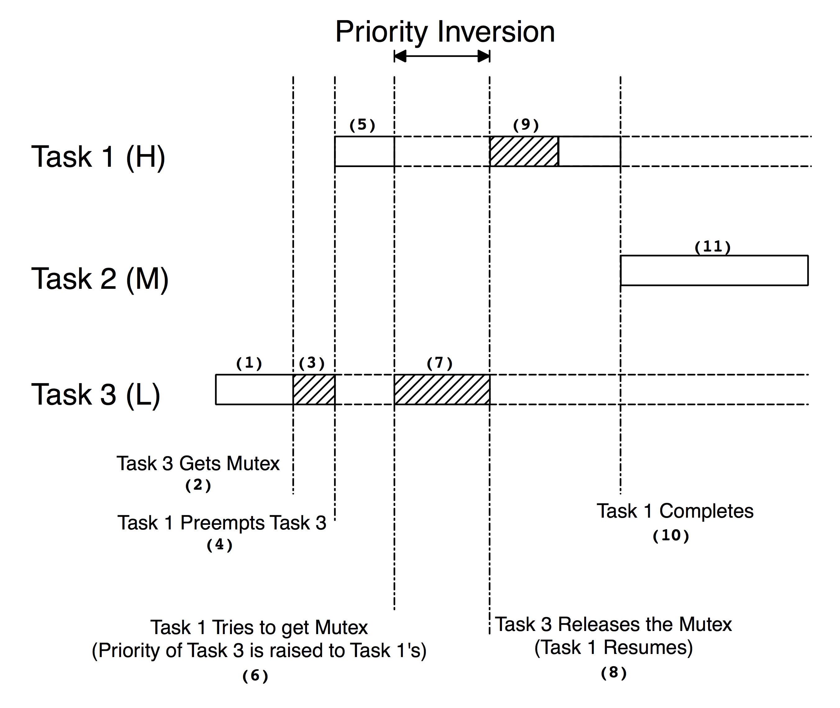
(1) & (2) As with the previous example, Task 3 is running but this time, acquires a mutual exclusion semaphore (also called a Mutex ) to access a shared resource.
(3) & (4) Task 3 accesses the resource and then is preempted by Task 1.
(5) & (6) Task 1 executes and tries to obtain the mutex. The kernel sees that Task 3 has the mutex and knows that Task 3 has a lower priority than Task 1. In this case, the kernel raises the priority of Task 3 to the same level as Task 1.
(7) The kernel places Task 1 in the mutex wait list and then resumes execution of Task 3 so that this task can continue with the resource.
(8) When Task 3 is done with the resource, it releases the mutex. At this point, the kernel reduces the priority of Task 3 to its original value and looks in the mutex wait list to see if a task is waiting for the mutex. The kernel sees that Task 1 is waiting and gives it the mutex.
(9) Task 1 is now free to access the resource.
(10) & (11) When Task 1 is done executing, the medium-priority task (i.e., Task 2) gets the CPU. Note that Task 2 could have been ready to run any time between F2.8(3) and F2.8(10) without affecting the outcome. There is still some level of priority inversion that cannot be avoided but far less than in the previous scenario.
Assigning Task Priorities
Assigning task priorities is not a trivial undertaking because of the complex nature of real-time systems. In most systems, not all tasks are considered critical. Noncritical tasks should obviously be given low priorities. Most real-time systems have a combination of SOFT and HARD requirements. In a SOFT real-time system, tasks are performed as quickly as possible, but they don’t have to finish by specific times. In HARD real-time systems, tasks have to be performed not only correctly, but on time.
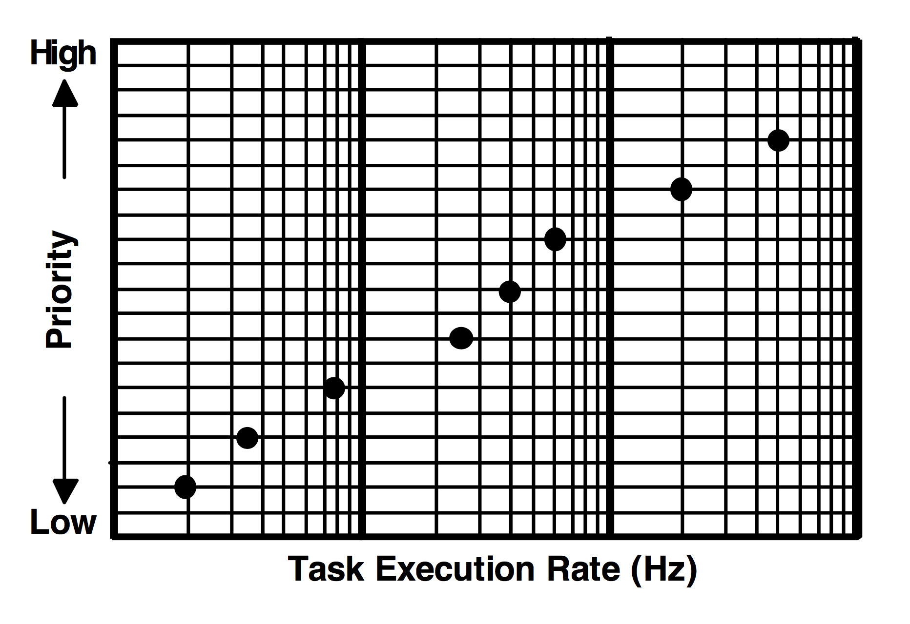
An interesting technique called Rate Monotonic Scheduling (RMS) has been established to assign task priorities based on how often tasks execute. Simply put, tasks with the highest rate of execution are given the highest priority (Figure 2.9).
RMS makes a number of assumptions:
- All tasks are periodic (they occur at regular intervals).
- Tasks do not synchronize with one another, share resources, or exchange data.
- The CPU must always execute the highest priority task that is ready to run. In other words, preemptive scheduling must be used.
Given a set of n tasks that are assigned RMS priorities, the basic RMS theorem states that all task HARD real-time deadlines will always be met if the inequality in Equation [2.1] is verified.
[2.1]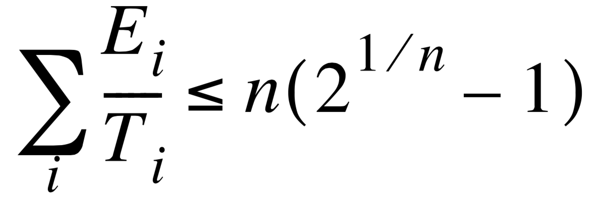
where, E i corresponds to the maximum execution time of task i and Ti corresponds to the execution period of task i. In other words, E i /T i corresponds to the fraction of CPU time required to execute task i. Table 2.1 shows the value for size n(21/ n - 1) based on the number of tasks. The upper bound for an infinite number of tasks is given by ln(2), or 0.693. This means that to meet all HARD real-time deadlines based on RMS, CPU utilization of all time-critical tasks should be less than 70 percent! Note that you can still have non-time-critical tasks in a system and thus use 100 percent of the CPU’s time. Using 100 percent of your CPU’s time is not a desirable goal because it does not allow for code changes and added features. As a rule of thumb, you should always design a system to use less than 60 to 70 percent of your CPU.
RMS says that the highest rate task has the highest priority. In some cases, the highest rate task may not be the most important task. Your application will thus dictate how you need to assign priorities. However, RMS is an interesting starting point.
Table 2.1 Allowable CPU utilization based on number of tasks.
| Number of Tasks | n(21/ n - 1) |
|---|---|
| 1 | 1.000 |
| 2 | 0.828 |
| 3 | 0.779 |
| 4 | 0.756 |
| 5 | 0.743 |
| . | . |
| . | . |
| . | . |
| ∞ | 0.693 |
Mutual Exclusion
The easiest way for tasks to communicate with each other is through shared data structures. This is especially easy when all tasks exist in a single address space and can reference global variables, pointers, buffers, linked lists, ring buffers, etc. Although sharing data simplifies the exchange of information, you must ensure that each task has exclusive access to the data to avoid contention and data corruption. The most common methods of obtaining exclusive access to shared resources are
- disabling interrupts,
- performing test-and-set operations,
- disabling scheduling, and
- using semaphores.
Disabling and Enabling Interrupts
The easiest and fastest way to gain exclusive access to a shared resource is by disabling and enabling interrupts, as shown in the pseudocode in Listing 2.3.
Disable interrupts;
Access the resource (read/write from/to variables);
Reenable interrupts;
µC/OS-II uses this technique (as do most, if not all, kernels) to access internal variables and data structures. In fact, µC/OS-II provides two macros that allow you to disable and then enable interrupts from your C code: OS_ENTER_CRITICAL() and OS_EXIT_CRITICAL() , respectively [see section ????, OS_ENTER_CRITICAL() , and OS_EXIT_CRITICAL() ]. You always need to use these macros in tandem, as shown in Listing 2.4.
void Function (void)
{
    OS_ENTER_CRITICAL();
    .
    .    /* You can access shared data in here */
    .
    OS_EXIT_CRITICAL();
}
You must be careful, however, not to disable interrupts for too long because this affects the response of your system to interrupts. This is known as interrupt latency. You should consider this method when you are changing or copying a few variables. Also, this is the only way that a task can share variables or data structures with an ISR. In all cases, you should keep interrupts disabled for as little time as possible.
If you use a kernel, you are basically allowed to disable interrupts for as much time as the kernel does without affecting interrupt latency. Obviously, you need to know how long the kernel will disable interrupts. Any good kernel vendor will provide you with this information. After all, if they sell a real-time kernel, time is important!
Test-And-Set
If you are not using a kernel, two functions could ‘agree’ that to access a resource, they must check a global variable and if the variable is 0, the function has access to the resource. To prevent the other function from accessing the resource, however, the first function that gets the resource simply sets the variable to 1. This is commonly called a Test-And-Set (or TAS) operation. Either the TAS operation must be performed indivisibly (by the processor) or you must disable interrupts when doing the TAS on the variable, as shown in Listing 2.5.
Disable interrupts;
if ('Access Variable' is 0) {
    Set variable to 1;
    Reenable interrupts;
    Access the resource;
    Disable interrupts;
    Set the 'Access Variable' back to 0;
    Reenable interrupts;
} else {
    Reenable interrupts;
    /* You don't have access to the resource, try back later; */
}
Some processors actually implement a TAS operation in hardware (e.g., the 68000 family of processors have the TAS instruction).
Disabling and Enabling the Scheduler
If your task is not sharing variables or data structures with an ISR, you can disable and enable scheduling (see section ???, Locking and Unlocking the Scheduler), as shown in Listing 2.6 (using µC/OS-II as an example). In this case, two or more tasks can share data without the possibility of contention. You should note that while the scheduler is locked, interrupts are enabled, and if an interrupt occurs while in the critical section, the ISR is executed immediately. At the end of the ISR, the kernel always returns to the interrupted task, even if a higher priority task has been made ready to run by the ISR. Because the ISR would return to the interrupted task, the behavior of the kernel is very similar to that of a non-preemptive kernel (at least, while the scheduler is locked). The scheduler is invoked when OSSchedUnlock() is called to see if a higher priority task has been made ready to run by the task or an ISR. A context switch results if a higher priority task is ready to run. Although this method works well, you should avoid disabling the scheduler because it defeats the purpose of having a kernel in the first place. The next method should be chosen instead.
void Function (void)
{
    OSSchedLock();
    .
    .    /* You can access shared data in here (interrupts are recognized) */
    .
    OSSchedUnlock();
}
Semaphores
The semaphore was invented by Edgser Dijkstra in the mid-1960s. It is a protocol mechanism offered by most multitasking kernels. Semaphores are used to
- control access to a shared resource (mutual exclusion),
- signal the occurrence of an event, and
- allow two tasks to synchronize their activities.
A semaphore is a key that your code acquires in order to continue execution. If the semaphore is already in use, the requesting task is suspended until the semaphore is released by its current owner. In other words, the requesting task says: “Give me the key. If someone else is using it, I am willing to wait for it!” There are two types of semaphores: binary semaphores and counting semaphores. As its name implies, a binary semaphore can only take two values: 0 or 1. A counting semaphore allows values between 0 and 255, 65535, or 4294967295, depending on whether the semaphore mechanism is implemented using 8, 16, or 32 bits, respectively. The actual size depends on the kernel used. Along with the semaphore’s value, the kernel also needs to keep track of tasks waiting for the semaphore’s availability.
Generally, only three operations can be performed on a semaphore: INITIALIZE (also called CREATE), WAIT (also called PEND), and SIGNAL (also called POST). The initial value of the semaphore must be provided when the semaphore is initialized. The waiting list of tasks is always initially empty.
A task desiring the semaphore will perform a WAIT operation. If the semaphore is available (the semaphore value is greater than 0), the semaphore value is decremented and the task continues execution. If the semaphore’s value is 0, the task performing a WAIT on the semaphore is placed in a waiting list. Most kernels allow you to specify a timeout; if the semaphore is not available within a certain amount of time, the requesting task is made ready to run and an error code (indicating that a timeout has occurred) is returned to the caller.
A task releases a semaphore by performing a SIGNAL operation. If no task is waiting for the semaphore, the semaphore value is simply incremented. If any task is waiting for the semaphore, however, one of the tasks is made ready to run and the semaphore value is not incremented; the key is given to one of the tasks waiting for it. Depending on the kernel, the task that receives the semaphore is either
- the highest priority task waiting for the semaphore or
- the first task that requested the semaphore (First In First Out, or FIFO).
Some kernels have an option that allows you to choose either method when the semaphore is initialized. µC/OS-II only supports the first method. If the readied task has a higher priority than the current task (the task releasing the semaphore), a context switch occurs (with a preemptive kernel) and the higher priority task resumes execution; the current task is suspended until it again becomes the highest priority task ready to run.
Listing 2.7 shows how you can share data using a semaphore (in µC/OS-II). Any task needing access to the same shared data calls OSSemPend(), and when the task is done with the data, the task calls OSSemPost(). Both of these functions are described later. You should note that a semaphore is an object that needs to be initialized before it’s used; for mutual exclusion, a semaphore is initialized to a value of 1. Using a semaphore to access shared data doesn’t affect interrupt latency. If an ISR or the current task makes a higher priority task ready to run while accessing shared data, the higher priority task executes immediately.
OS_EVENT *SharedDataSem;
void Function (void)
{
    INT8U err;

    OSSemPend(SharedDataSem, 0, &err);
    .
    .    /* You can access shared data in here (interrupts are recognized) */
    .
    OSSemPost(SharedDataSem);
}
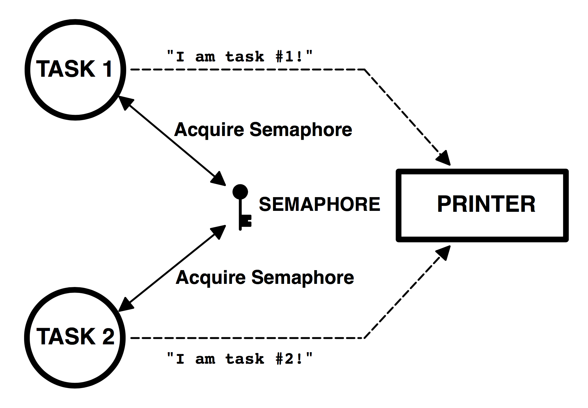
Semaphores are especially useful when tasks share I/O devices. Imagine what would happen if two tasks were allowed to send characters to a printer at the same time. The printer would contain interleaved data from each task. For instance, the printout from Task 1 printing “I am Task 1!” and Task 2 printing “I am Task 2!” could result in:
I Ia amm T Tasask k1 !2!
In this case, use a semaphore and initialize it to 1 (i.e., a binary semaphore). The rule is simple: to access the printer each task first must obtain the resource’s semaphore. Figure 2.10 shows tasks competing for a semaphore to gain exclusive access to the printer. Note that the semaphore is represented symbolically by a key, indicating that each task must obtain this key to use the printer.
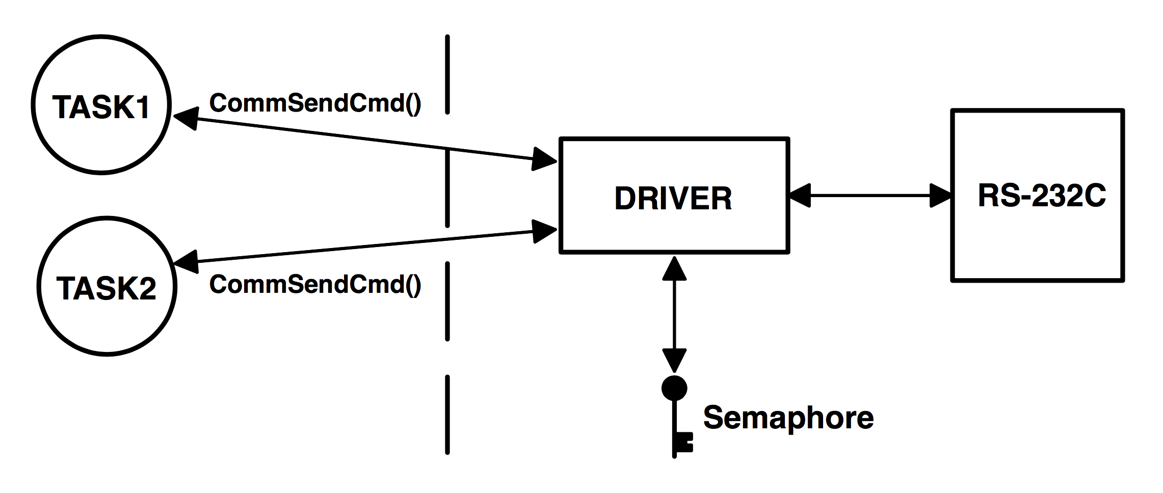
The above example implies that each task must know about the existence of the semaphore in order to access the resource. There are situations when it is better to encapsulate the semaphore. Each task would thus not know that it is actually acquiring a semaphore when accessing the resource. For example, an RS-232C port is used by multiple tasks to send commands and receive responses from a device connected at the other end (Figure 2.11).
The function CommSendCmd() is called with three arguments: the ASCII string containing the command, a pointer to the response string from the device, and finally, a timeout in case the device doesn’t respond within a certain amount of time. The pseudocode for this function is shown in Listing 2.8.
INT8U CommSendCmd(char *cmd, char *response, INT16U timeout)
{
    Acquire port's semaphore;
    Send command to device;
    Wait for response (with timeout);
    if (timed out) {
       Release semaphore;
       return (error code);
    } else {
        Release semaphore;
        return (no error);
    }
}
Each task that needs to send a command to the device has to call this function. The semaphore is assumed to be initialized to 1 (i.e., available) by the communication driver initialization routine. The first task that calls CommSendCmd() acquires the semaphore, proceeds to send the command, and waits for a response. If another task attempts to send a command while the port is busy, this second task is suspended until the semaphore is released. The second task appears simply to have made a call to a normal function that will not return until the function has performed its duty. When the semaphore is released by the first task, the second task acquires the semaphore and is allowed to use the RS-232C port.
A counting semaphore is used when a resource can be used by more than one task at the same time. For example, a counting semaphore is used in the management of a buffer pool as shown in Figure 2.12. Assume that the buffer pool initially contains 10 buffers. A task would obtain a buffer from the buffer manager by calling BufReq() . When the buffer is no longer needed, the task would return the buffer to the buffer manager by calling BufRel() . The pseudocode for these functions is shown in Listing 2.9.
BUF *BufReq(void)
{
   BUF *ptr;

   Acquire a semaphore;
   Disable interrupts;
   ptr         = BufFreeList;
   BufFreeList = ptr->BufNext;
   Enable interrupts;
   return (ptr);
}


void BufRel(BUF *ptr)
{
   Disable interrupts;
   ptr->BufNext = BufFreeList;
   BufFreeList  = ptr;
   Enable interrupts;
   Release semaphore;
}
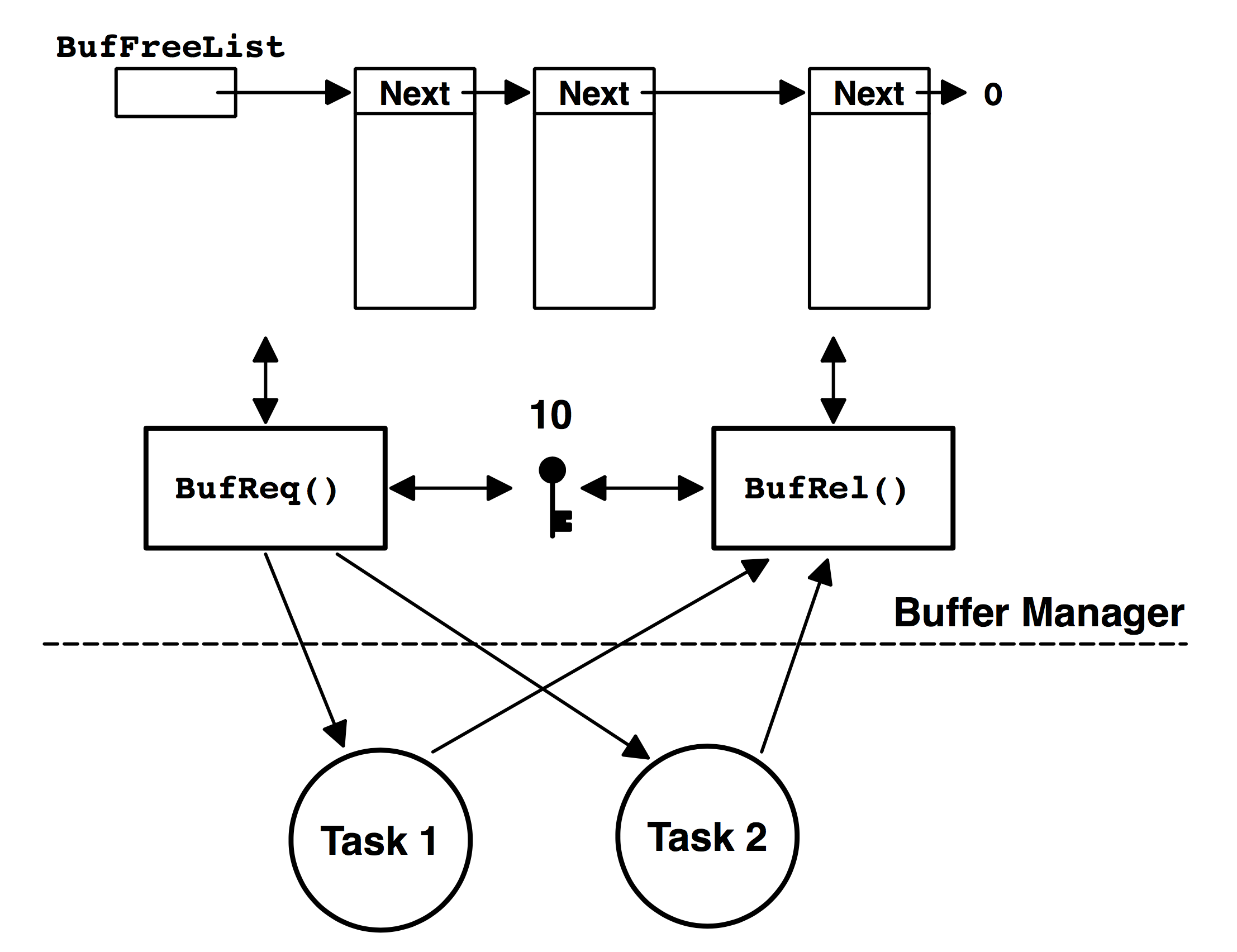
The buffer manager will satisfy the first 10 buffer requests because there are 10 keys. When all semaphores are used, a task requesting a buffer is suspended until a semaphore becomes available. Interrupts are disabled to gain exclusive access to the linked list (this operation is very quick). When a task is finished with the buffer it acquired, it calls BufRel() to return the buffer to the buffer manager; the buffer is inserted into the linked list before the semaphore is released. By encapsulating the interface to the buffer manager in BufReq() and BufRel() , the caller doesn’t need to be concerned with the actual implementation details.
Semaphores are often overused. The use of a semaphore to access a simple shared variable is overkill in most situations. The overhead involved in acquiring and releasing the semaphore can consume valuable time. You can do the job just as efficiently by disabling and enabling interrupts (see section 2.18.01, Disabling and Enabling Interrupts). Suppose that two tasks are sharing a 32-bit integer variable. The first task increments the variable while the other task clears it. If you consider how long a processor takes to perform either operation, you will realize that you do not need a semaphore to gain exclusive access to the variable. Each task simply needs to disable interrupts before performing its operation on the variable and enable interrupts when the operation is complete. A semaphore should be used, however, if the variable is a floating-point variable and the microprocessor doesn’t support floating point in hardware. In this case, the processing time involved in processing the floating-point variable could have affected interrupt latency if you had disabled interrupts.
Deadlock (or Deadly Embrace)
A deadlock, also called a deadly embrace, is a situation in which two tasks are each unknowingly waiting for resources held by the other. Assume task T1 has exclusive access to resource R1 and task T2 has exclusive access to resource R2. If T1 needs exclusive access to R2 and T2 needs exclusive access to R1, neither task can continue. They are deadlocked. The simplest way to avoid a deadlock is for tasks to
- acquire all resources before proceeding,
- acquire the resources in the same order, and
- release the resources in the reverse order.
Most kernels allow you to specify a timeout when acquiring a semaphore. This feature allows a deadlock to be broken. If the semaphore is not available within a certain amount of time, the task requesting the resource resumes execution. Some form of error code must be returned to the task to notify it that a timeout occurred. A return error code prevents the task from thinking it has obtained the resource. Deadlocks generally occur in large multitasking systems, not in embedded systems (at least they better not!).
Synchronization
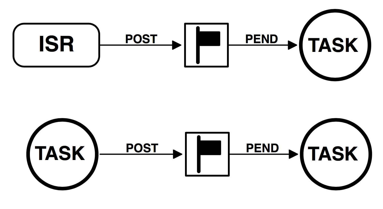
A task can be synchronized with an ISR (or another task when no data is being exchanged) by using a semaphore as shown in Figure 2.13. Note that, in this case, the semaphore is drawn as a flag to indicate that it is used to signal the occurrence of an event (rather than to ensure mutual exclusion, in which case it would be drawn as a key). When used as a synchronization mechanism, the semaphore is initialized to 0. Using a semaphore for this type of synchronization is called a unilateral rendezvous. For example, a task can initiate an I/O operation and then waits for the semaphore. When the I/O operation is complete, an ISR (or another task) signals the semaphore and the task is resumed.
If the kernel supports counting semaphores, the semaphore would accumulate events that have not yet been processed. Note that more than one task can be waiting for an event to occur. In this case, the kernel could signal the occurrence of the event either to
- the highest priority task waiting for the event to occur or
- the first task waiting for the event.
Depending on the application, more than one ISR or task could signal the occurrence of the event.
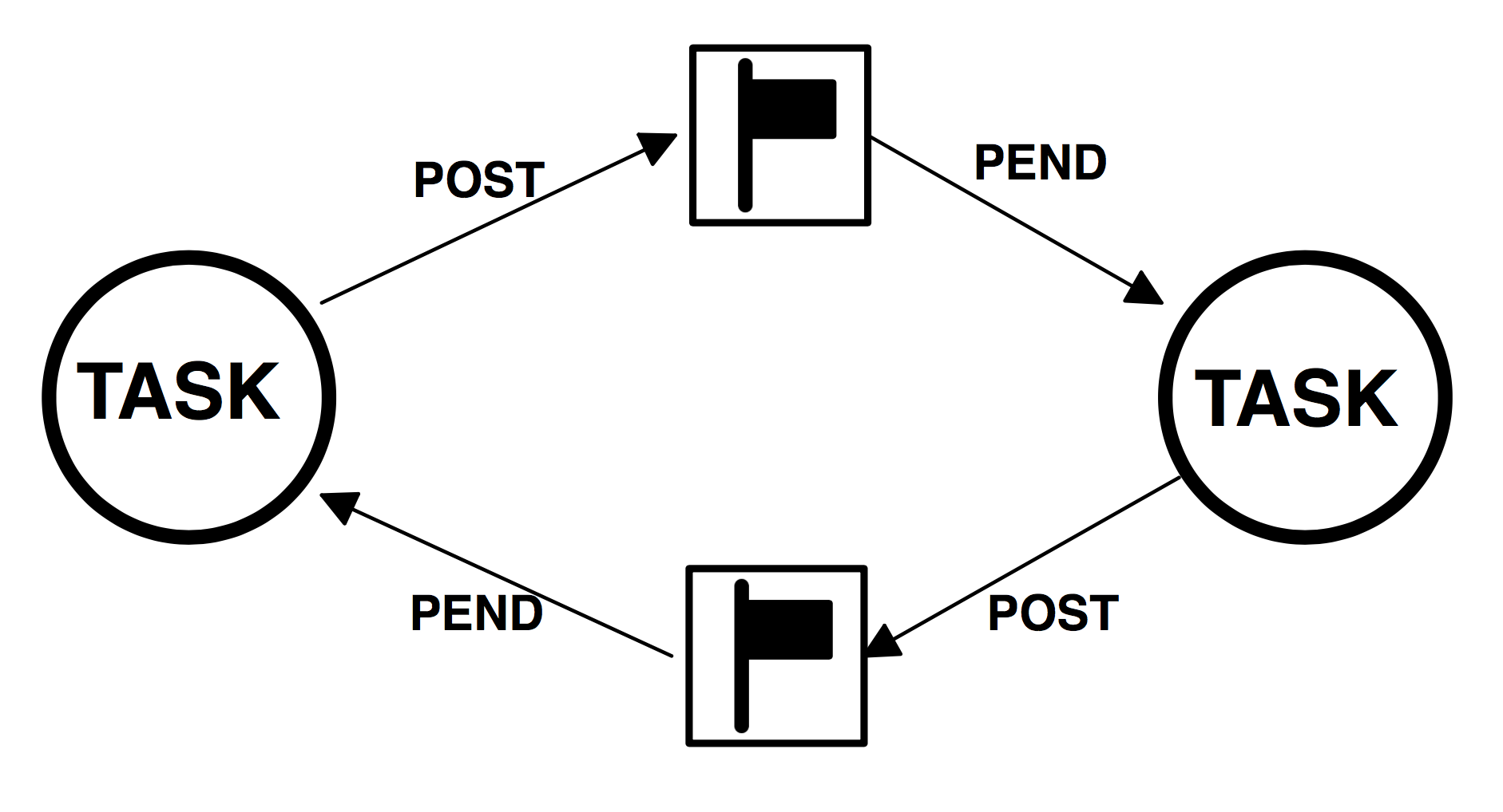
Two tasks can synchronize their activities by using two semaphores, as shown in Figure 2.14. This is called a bilateral rendezvous. A bilateral rendezvous is similar to a unilateral rendezvous, except both tasks must synchronize with one another before proceeding. A bilateral rendezvous cannot be performed between a task and an ISR because an ISR cannot wait on a semaphore.
For example, two tasks are executing as shown in Listing 2.10.
Task1()
{
    for (;;) {
       Perform operation;
       Signal task #2;                                                    (1)
       Wait for signal from task #2;                                      (2)
       Continue operation;
    }
}

Task2()
{
    for (;;) {
       Perform operation;
       Signal task #1;                                                    (3)
       Wait for signal from task #1;                                      (4)
       Continue operation;
    }
}
(1) & (2) When the first task reaches a certain point, it signals the second task then waits for a return signal.
(3) & (4) Similarly, when the second task reaches a certain point, it signals the first task and waits for a return signal. At this point, both tasks are synchronized with each other.
Event Flags
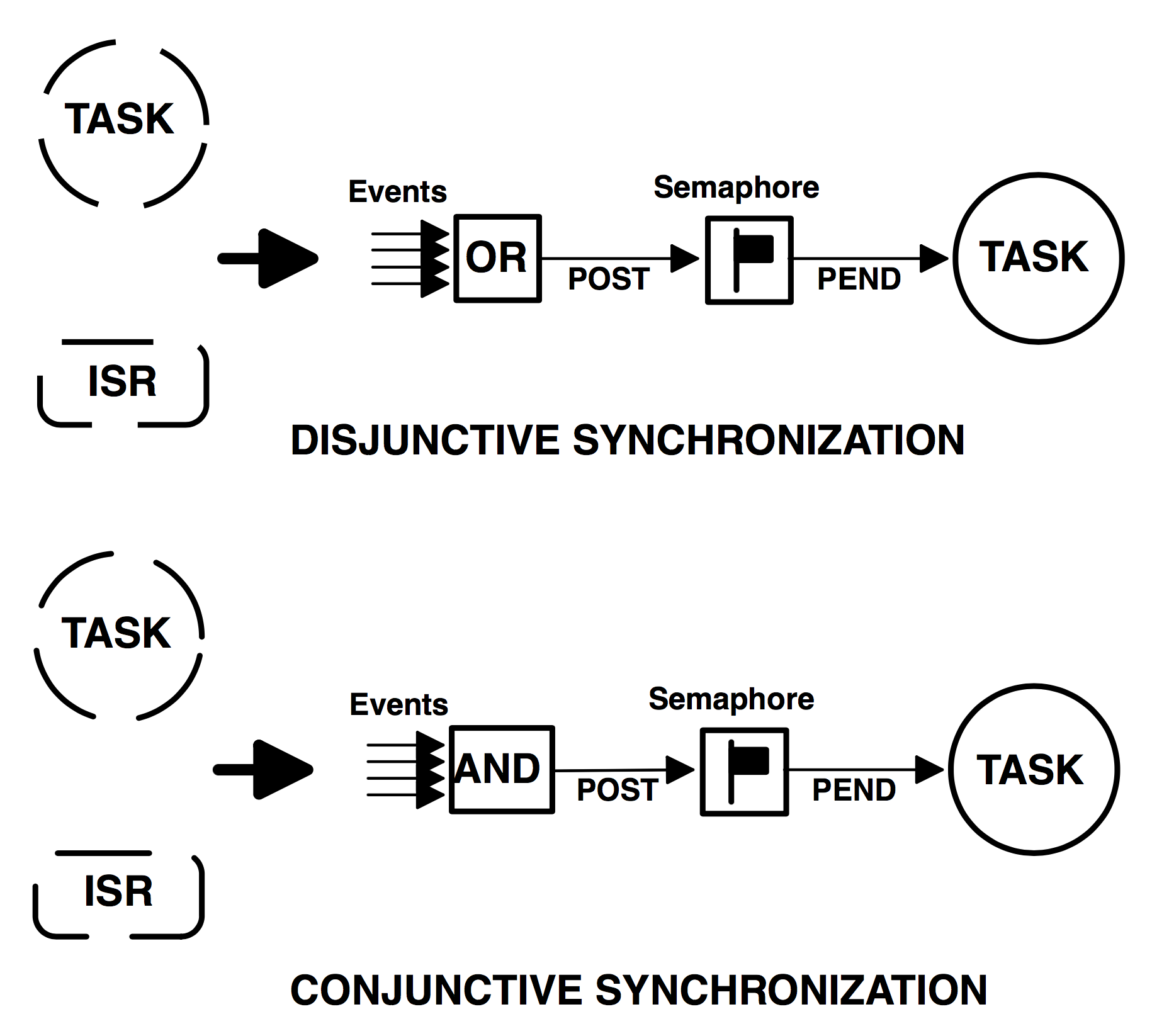
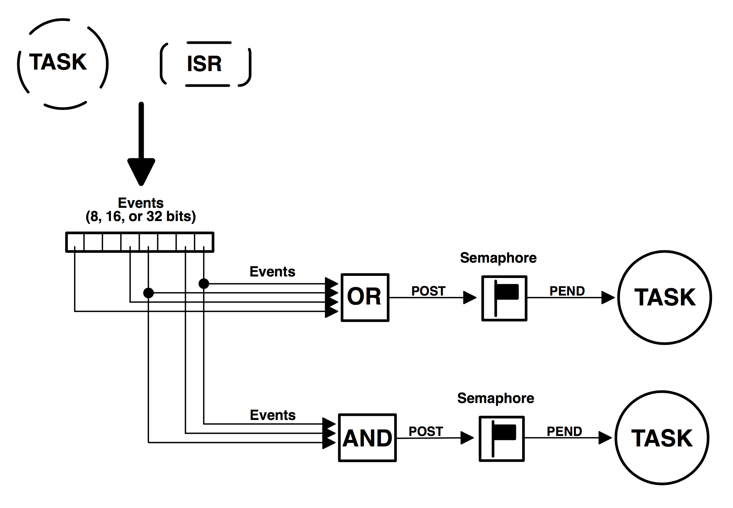
Event flags are used when a task needs to synchronize with the occurrence of multiple events. The task can be synchronized when any of the events have occurred. This is called disjunctive synchronization (logical OR). A task can also be synchronized when all events have occurred. This is called conjunctive synchronization (logical AND). Disjunctive and conjunctive synchronization are shown in Figure 2.15.
Common events can be used to signal multiple tasks, as shown in Figure 2.16. Events are typically grouped. Depending on the kernel, a group consists of 8, 16, or 32 events, each represented by a bit. (mostly 32 bits, though). Tasks and ISRs can set or clear any event in a group. A task is resumed when all the events it requires are satisfied. The evaluation of which task will be resumed is performed when a new set of events occurs (i.e., during a SET operation).
Kernels like µC/OS-II which support event flags offer services to SET event flags, CLEAR event flags, and WAIT for event flags (conjunctively or disjunctively).
Intertask Communication
It is sometimes necessary for a task or an ISR to communicate information to another task. This information transfer is called intertask communication. Information may be communicated between tasks in two ways: through global data or by sending messages.
When using global variables, each task or ISR must ensure that it has exclusive access to the variables. If an ISR is involved, the only way to ensure exclusive access to the common variables is to disable interrupts. If two tasks are sharing data, each can gain exclusive access to the variables either by disabling and enabling interrupts or with the use of a semaphore (as we have seen). Note that a task can only communicate information to an ISR by using global variables. A task is not aware when a global variable is changed by an ISR, unless the ISR signals the task by using a semaphore or unless the task polls the contents of the variable periodically. To correct this situation, you should consider using either a message mailbox or a message queue.
Message Mailboxes
Messages can be sent to a task through kernel services. A Message Mailbox, also called a message exchange, is typically a pointer-size variable. Through a service provided by the kernel, a task or an ISR can deposit a message (the pointer) into this mailbox. Similarly, one or more tasks can receive messages through a service provided by the kernel. Both the sending task and receiving task agree on what the pointer is actually pointing to.
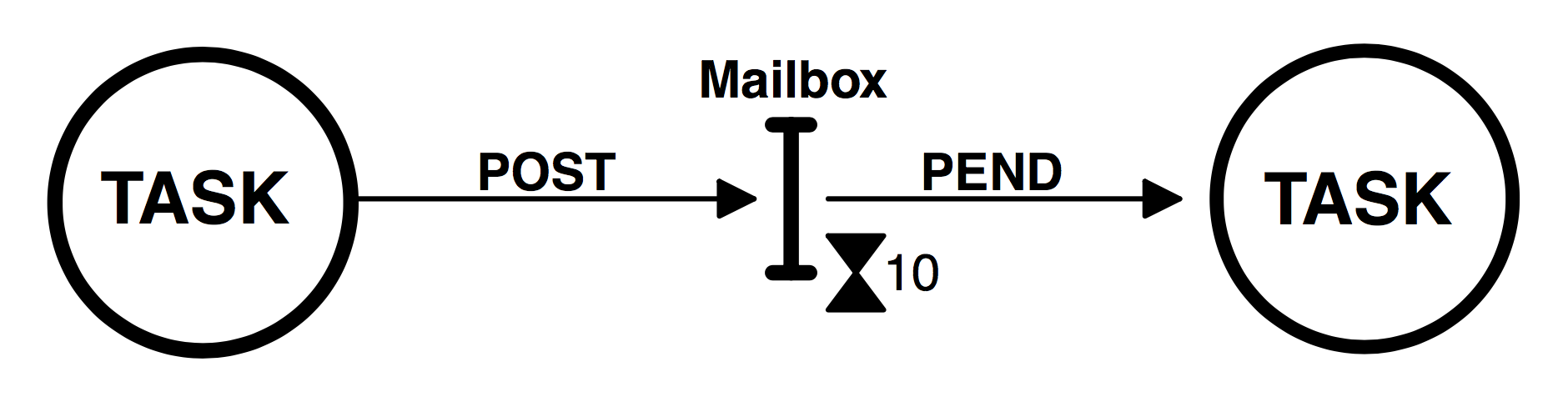
A waiting list is associated with each mailbox in case more than one task wants to receive messages through the mailbox. A task desiring a message from an empty mailbox is suspended and placed on the waiting list until a message is received. Typically, the kernel allows the task waiting for a message to specify a timeout. If a message is not received before the timeout expires, the requesting task is made ready to run and an error code (indicating that a timeout has occurred) is returned to it. When a message is deposited into the mailbox, either the highest priority task waiting for the message is given the message (priority based) or the first task to request a message is given the message (First-In-First-Out, or FIFO). µC/OS-II only supports the first mechanism – gives the message to the highest priority task waiting. Figure 2.17 shows a task depositing a message into a mailbox. Note that the mailbox is represented by an I-beam and the timeout is represented by an hourglass. The number next to the hourglass represents the number of clock ticks (described later) the task will wait for a message to arrive.
Kernels typically provide the following mailbox services.
- Initialize the contents of a mailbox. The mailbox initially may or may not contain a message.
- Deposit a message into the mailbox (POST).
- Wait for a message to be deposited into the mailbox (PEND).
- Get a message from a mailbox if one is present, but do not suspend the caller if the mailbox is empty (ACCEPT). If the mailbox contains a message, the message is extracted from the mailbox. A return code is used to notify the caller about the outcome of the call.
Message mailboxes can also simulate binary semaphores. A message in the mailbox indicates that the resource is available, and an empty mailbox indicates that the resource is already in use by another task.
Message Queues
A message queue is used to send one or more messages to a task. A message queue is basically an array of mailboxes. Through a service provided by the kernel, a task or an ISR can deposit a message (the pointer) into a message queue. Similarly, one or more tasks can receive messages through a service provided by the kernel. Both the sending task and receiving task or tasks have to agree as to what the pointer is actually pointing to. Generally, the first message inserted in the queue will be the first message extracted from the queue (FIFO). In addition, to extract messages in a FIFO fashion, µC/OS-II allows a task to get messages Last-In-First-Out (LIFO).
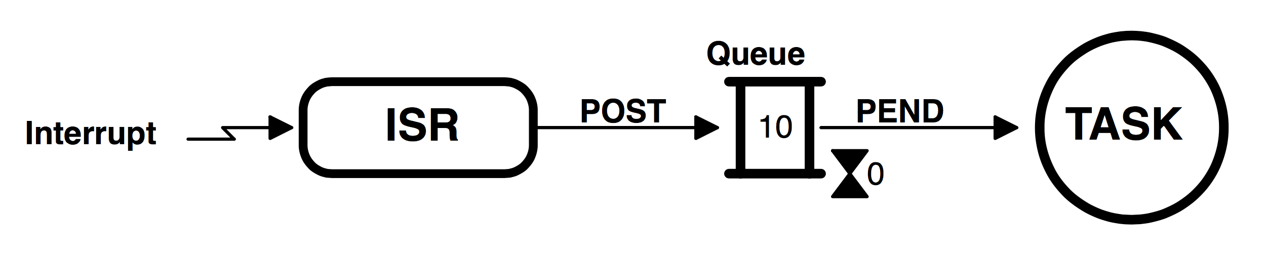
As with the mailbox, a waiting list is associated with each message queue, in case more than one task is to receive messages through the queue. A task desiring a message from an empty queue is suspended and placed on the waiting list until a message is received. Typically, the kernel allows the task waiting for a message to specify a timeout. If a message is not received before the timeout expires, the requesting task is made ready to run and an error code (indicating a timeout has occurred) is returned to it. When a message is deposited into the queue, either the highest priority task or the first task to wait for the message is given the message. µC/OS-II only supports the first mechanism – gives the message to the highest priority task waiting. Figure 2.18 shows an ISR (Interrupt Service Routine) depositing a message into a queue. Note that the queue is represented graphically by a double I-beam. The “10” indicates the number of messages that can accumulate in the queue. A “0” next to the hourglass indicates that the task will wait forever for a message to arrive.
Kernels typically provide the message queue services listed below.
- Initialize the queue. The queue is always assumed to be empty after initialization.
- Deposit a message into the queue (POST).
- Wait for a message to be deposited into the queue (PEND).
- Get a message from a queue if one is present, but do not suspend the caller if the queue is empty (ACCEPT). If the queue contains a message, the message is extracted from the queue. A return code is used to notify the caller about the outcome of the call.
Interrupts
An interrupt is a hardware mechanism used to inform the CPU that an asynchronous event has occurred. When an interrupt is recognized, the CPU saves part (or all) of its context (i.e., registers) and jumps to a special subroutine called an Interrupt Service Routine, or ISR. The ISR processes the event, and upon completion of the ISR, the program returns to
- the background for a foreground/background system,
- the interrupted task for a non-preemptive kernel, or
- the highest priority task ready to run for a preemptive kernel.
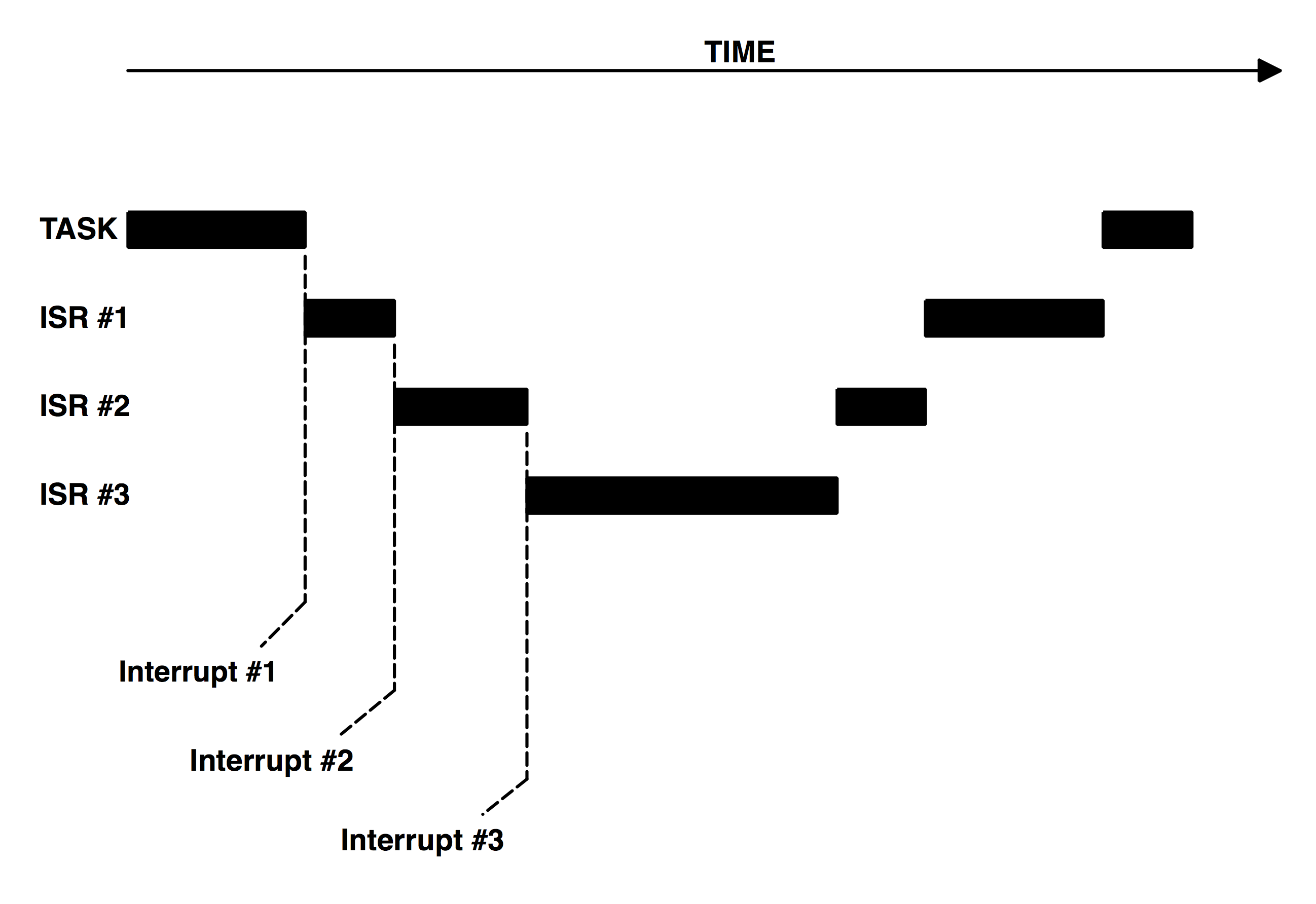
Interrupts allow a microprocessor to process events when they occur. This prevents the microprocessor from continuously polling (looking at) an event to see if it has occurred. Microprocessors allow interrupts to be ignored and recognized through the use of two special instructions: disable interrupts and enable interrupts, respectively. In a real-time environment, interrupts should be disabled as little as possible. Disabling interrupts affects interrupt latency (see section 2.26, Interrupt Latency) and may cause interrupts to be missed. Processors generally allow interrupts to be nested. This means that while servicing an interrupt, the processor will recognize and service other (more important) interrupts, as shown in Figure 2.19.
Interrupt Latency
Probably the most important specification of a real-time kernel is the amount of time interrupts are disabled. All real-time systems disable interrupts to manipulate critical sections of code and reenable interrupts when the critical section has executed. The longer interrupts are disabled, the higher the interrupt latency. Interrupt latency is given by Equation [2.2].
[2.2] Maximum amount of time interrupts are disabled
+ Time to start executing the first instruction in the ISR
Interrupt Response
Interrupt response is defined as the time between the reception of the interrupt and the start of the user code that handles the interrupt. The interrupt response time accounts for all the overhead involved in handling an interrupt. Typically, the processor’s context (CPU registers) is saved on the stack before the user code is executed.
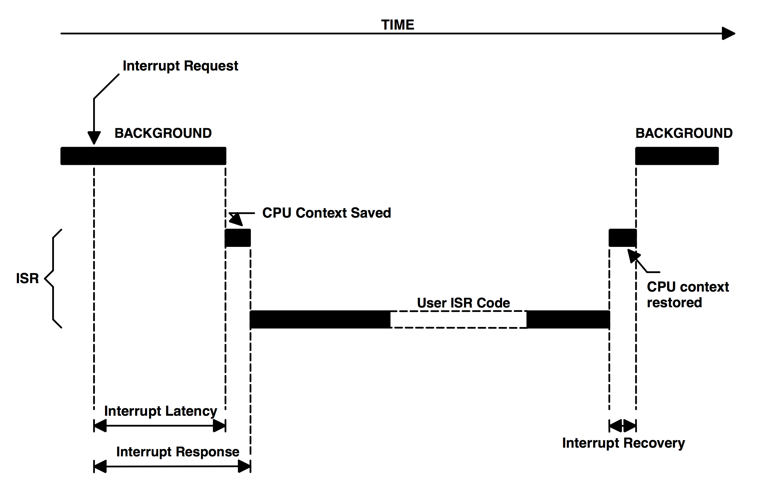
For a foreground/background system, the user ISR code is executed immediately after saving the processor’s context. The response time is given by Equation [2.3].
[2.3] Interrupt latency + Time to save the CPU’s context
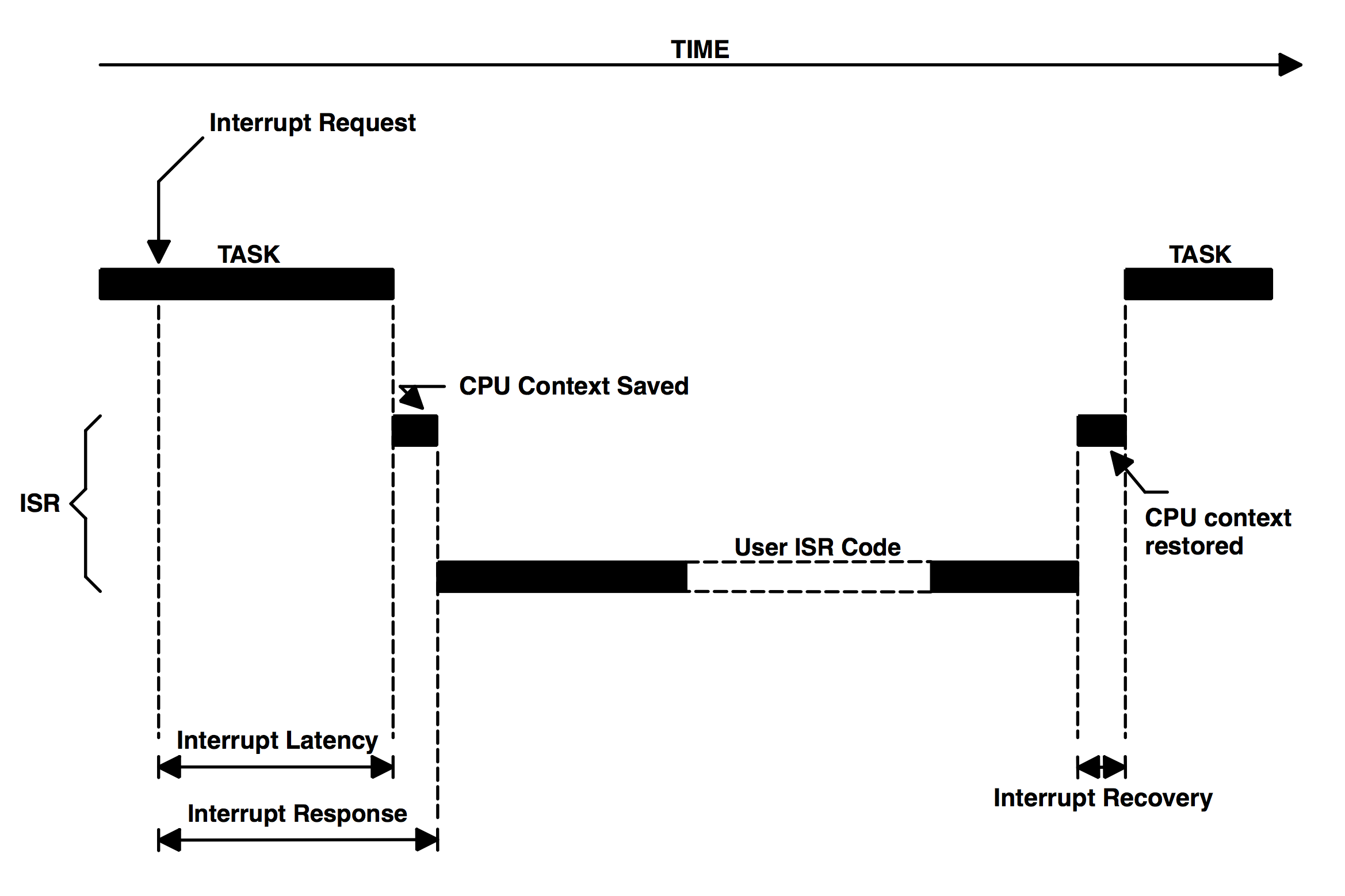
For a non-preemptive kernel, the user ISR code is executed immediately after the processor’s context is saved. The response time to an interrupt for a non-preemptive kernel is given by Equation [2.4].
[2.4] Interrupt latency + Time to save the CPU’s context
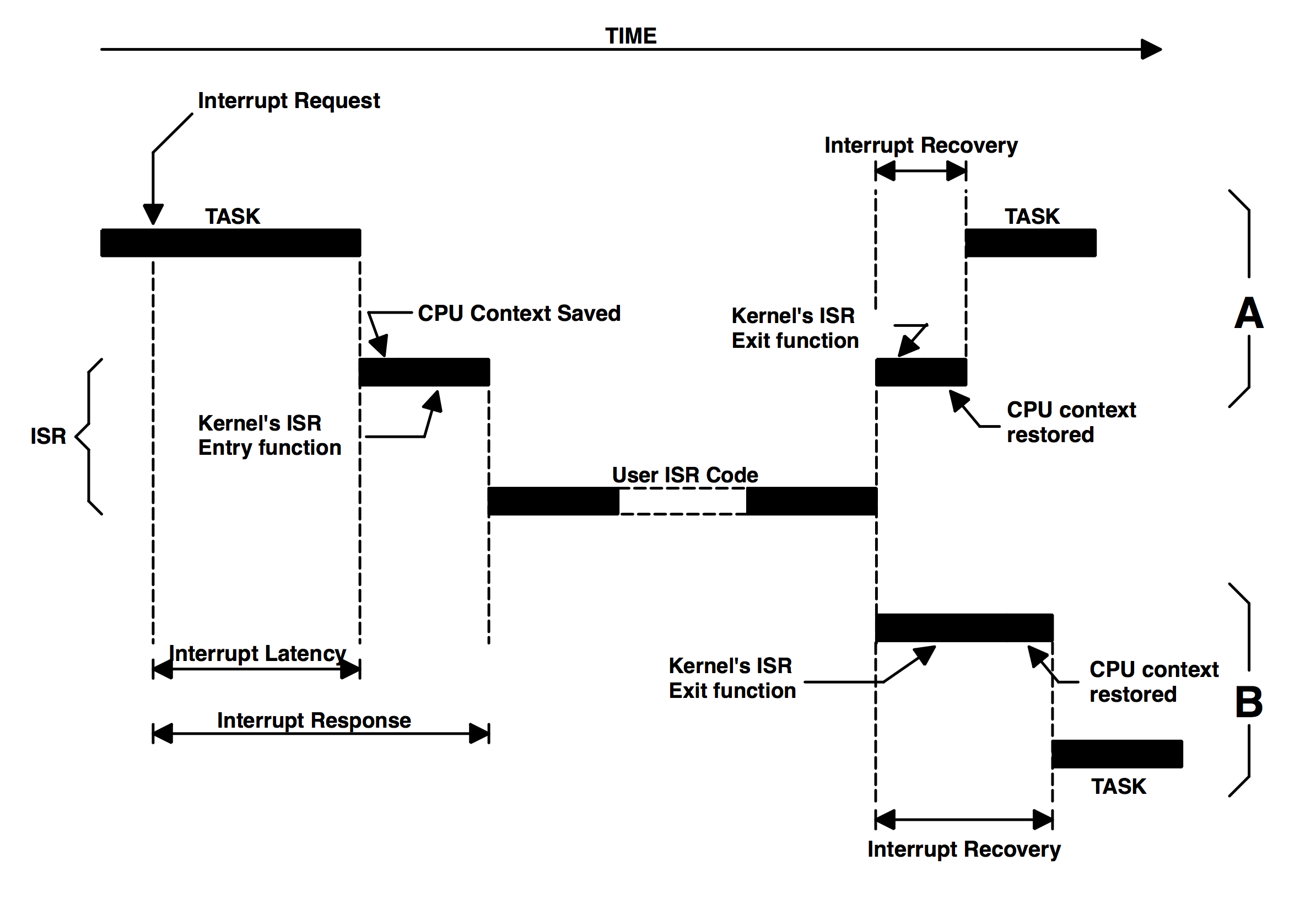
For a preemptive kernel, a special function provided by the kernel needs to be called to notify the kernel that an ISR is starting. This function allows the kernel to keep track of interrupt nesting. The reason this function is needed will be explained in section 2.28, Interrupt Recovery. For µC/OS-II, this function is called OSIntEnter(). The response time to an interrupt for a preemptive kernel is given by Equation [2.5].
[2.5] Interrupt latency
+ Time to save the CPU’s context
+ Execution time of the kernel ISR entry function
A system’s worst case interrupt response time is its only response. Your system may respond to interrupts in 50ms 99 percent of the time, but if it responds to interrupts in 250ms the other 1 percent, you must assume a 250ms interrupt response time.
Interrupt Recovery
Interrupt recovery is defined as the time required for the processor to return to the interrupted code or to a higher priority task in the case of a preemptive kernel. Interrupt recovery in a foreground/background system simply involves restoring the processor’s context and returning to the interrupted task. Interrupt recovery is given by Equation [2.6].
[2.6] Time to restore the CPU’s context
+ Time to execute the return from interrupt instruction
As with a foreground/background system, interrupt recovery with a non-preemptive kernel (Equation [2.7]) simply involves restoring the processor’s context and returning to the interrupted task.
[2.7] Time to restore the CPU’s context
+ Time to execute the return from interrupt instruction
For a preemptive kernel, interrupt recovery is more complex. Typically, a function provided by the kernel is called at the end of the ISR. For µC/OS-II, this function is called OSIntExit() and allows the kernel to determine if all interrupts have nested. If they have nested (i.e., a return from interrupt would return to task-level code), the kernel determines if a higher priority task has been made ready-to-run as a result of the ISR. If a higher priority task is ready-to-run as a result of the ISR, this task is resumed. Note that, in this case, the interrupted task will resume only when it again becomes the highest priority task ready-to-run. For a preemptive kernel, interrupt recovery is given by Equation [2.8].
[2.8] Time to determine if a higher priority task is ready
+ Time to restore the CPU’s context of the highest priority task
+ Time to execute the return from interrupt instruction
Interrupt Latency, Response, and Recovery
Figures 2.20 through 2.22 show the interrupt latency, response, and recovery for a foreground/background system, a non-preemptive kernel, and a preemptive kernel, respectively.
You should note that for a preemptive kernel, the exit function either decides to return to the interrupted task [F2.22(A)] or to a higher priority task that the ISR has made ready to run [F2.22(B)]. In the later case, the execution time is slightly longer because the kernel has to perform a context switch. I made the difference in execution time somewhat to scale assuming µC/OS-II on an Intel 80186 processor (see Table 14.3, Execution times of µC/OS-II services on 33MHz 80186). This allows you to see the cost (in execution time) of switching context.
ISR Processing Time
Although ISRs should be as short as possible, there are no absolute limits on the amount of time for an ISR. One cannot say that an ISR must always be less than 100ms, 500ms, or 1ms. If the ISR code is the most important code that needs to run at any given time, it could be as long as it needs to be. In most cases, however, the ISR should recognize the interrupt, obtain data or a status from the interrupting device, and signal a task to perform the actual processing. You should also consider whether the overhead involved in signaling a task is more than the processing of the interrupt. Signaling a task from an ISR (i.e., through a semaphore, a mailbox, or a queue) requires some processing time. If processing your interrupt requires less than the time required to signal a task, you should consider processing the interrupt in the ISR itself and possibly enabling interrupts to allow higher priority interrupts to be recognized and serviced.
Nonmaskable Interrupts (NMIs)
Sometimes, an interrupt must be serviced as quickly as possible and cannot afford to have the latency imposed by a kernel. In these situations, you may be able to use the Nonmaskable Interrupt (NMI) provided on most microprocessors. Because the NMI cannot be disabled, interrupt latency, response, and recovery are minimal. The NMI is generally reserved for drastic measures such as saving important information during a power down. If, however, your application doesn’t have this requirement, you could use the NMI to service your most time-critical ISR. The following equations show how to determine the interrupt latency [2.9], response [2.10], and recovery [2.11], respectively, of an NMI.
[2.9] Interrupt Latency =
Time to execute longest instruction
+ Time to start executing the NMI ISR
[2.10] Interrupt Response =
Interrupt latency
+ Time to save the CPU’s context
[2.11] Interrupt Recovery =
     Time to restore the CPU’s context
        + Time to execute the return from interrupt instruction
I have used the NMI in an application to respond to an interrupt that could occur every 150ms. The processing time of the ISR took from 80 to 125ms, and the kernel I used had an interrupt response of about 45ms. As you can see, if I had used maskable interrupts, the ISR could have been late by 20ms (125µs + 45µs > 150µs).
When you are servicing an NMI, you cannot use kernel services to signal a task because NMIs cannot be disabled to access critical sections of code. However, you can still pass parameters to and from the NMI. Parameters passed must be global variables and the size of these variables must be read or written indivisibly; that is, not as separate byte read or write instructions.
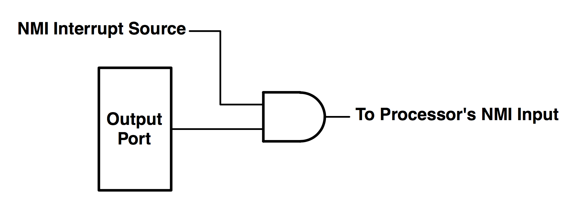
NMIs can be disabled by adding external circuitry, as shown in Figure 2.23. Assuming that both the interrupt and the NMI are positive-going signals, a simple AND gate is inserted between the interrupt source and the processor’s NMI input. Interrupts are disabled by writing a 0 to an output port. You wouldn’t want to disable interrupts to use kernel services, but you could use this feature to pass parameters (i.e., larger variables) to and from the ISR and a task.
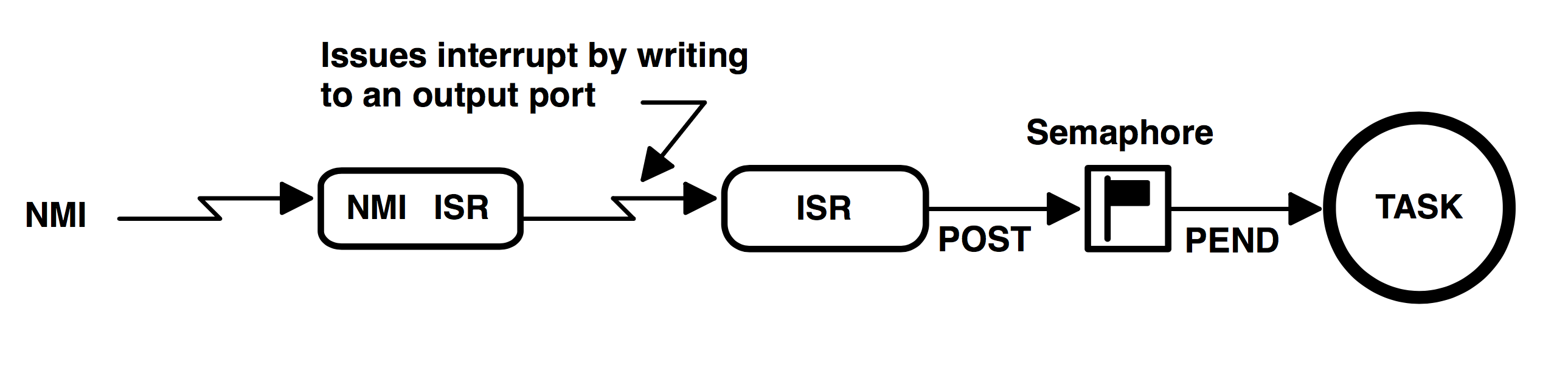
Now, suppose that the NMI service routine needs to signal a task every 40 times it executes. If the NMI occurs every 150ms, a signal would be required every 6ms (40 x 150ms). From a NMI ISR, you cannot use the kernel to signal the task, but you could use the scheme shown in Figure 2.24. In this case, the NMI service routine would generate a hardware interrupt through an output port (i.e., bring an output high). Since the NMI service routine typically has the highest priority and interrupt nesting is typically not allowed while servicing the NMI ISR, the interrupt would not be recognized until the end of the NMI service routine. At the completion of the NMI service routine, the processor would be interrupted to service this hardware interrupt. This ISR would clear the interrupt source (i.e., bring the port output low) and post to a semaphore that would wake up the task. As long as the task services the semaphore well within 6ms, your deadline would be met.
Clock Tick
A clock tick is a special interrupt that occurs periodically. This interrupt can be viewed as the system’s heartbeat. The time between interrupts is application specific and is generally between 10 and 200ms. The clock tick interrupt allows a kernel to delay tasks for an integral number of clock ticks and to provide timeouts when tasks are waiting for events to occur. The faster the tick rate, the higher the overhead imposed on the system.
All kernels allow tasks to be delayed for a certain number of clock ticks. The resolution of delayed tasks is one clock tick; however, this does not mean that its accuracy is one clock tick.
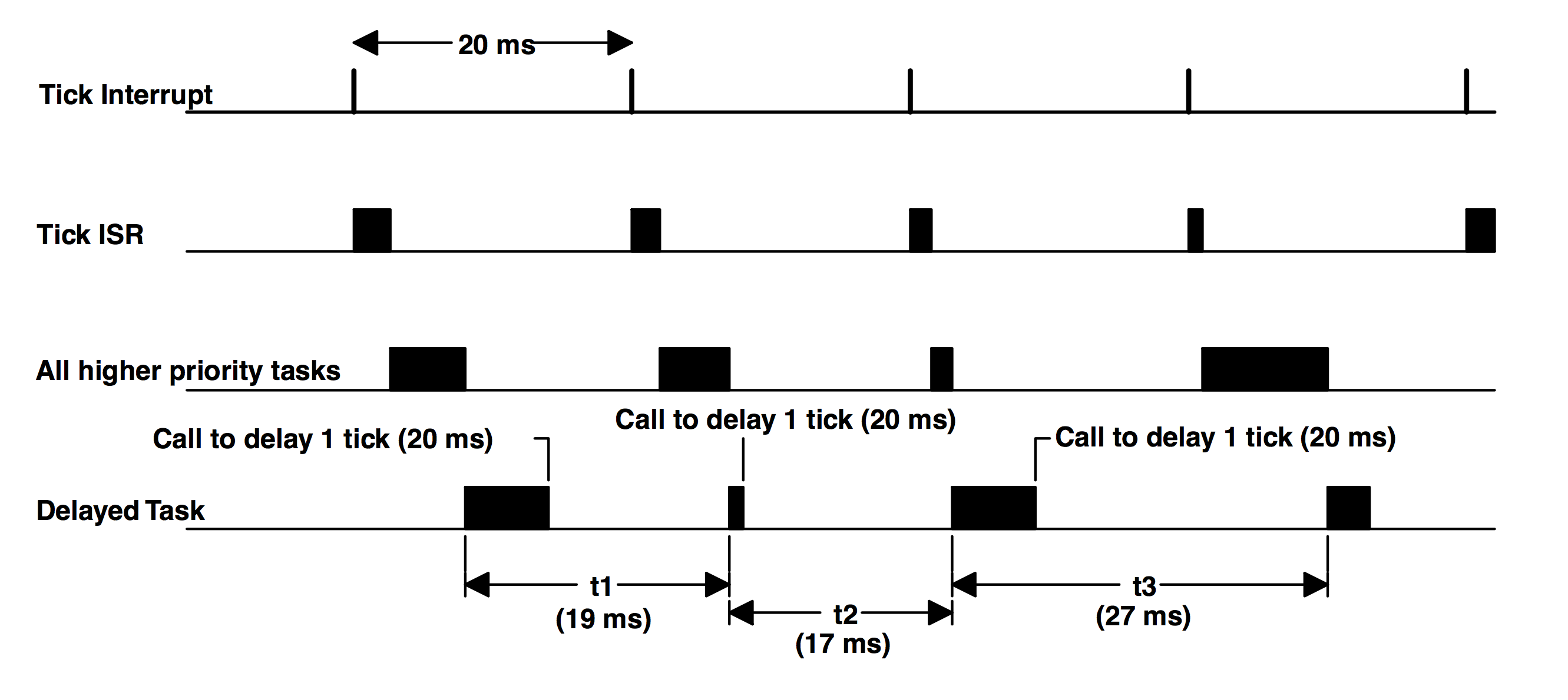
Figures 2.25 through 2.27 are timing diagrams showing a task delaying itself for one clock tick. The shaded areas indicate the execution time for each operation being performed. Note that the time for each operation varies to reflect typical processing, which would include loops and conditional statements (i.e., if/else, switch, and ?:). The processing time of the Tick ISR has been exaggerated to show that it too is subject to varying execution times.
Case 1 (Figure 2.25) shows a situation where higher priority tasks and ISRs execute prior to the task, which needs to delay for one tick. As you can see, the task attempts to delay for 20ms but because of its priority, actually executes at varying intervals. This causes the execution of the task to jitter.
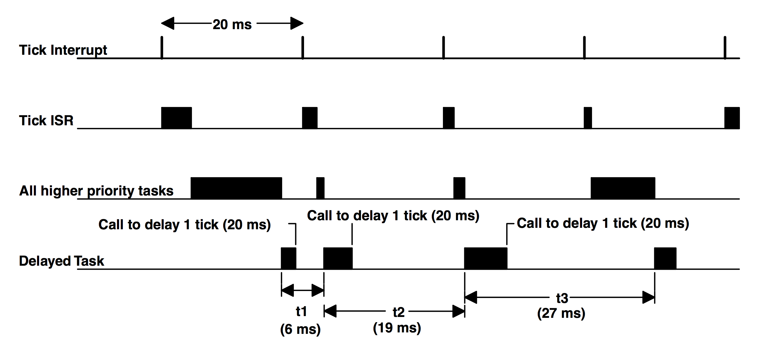
Case 2 (Figure 2.26) shows a situation where the execution times of all higher priority tasks and ISRs are slightly less than one tick. If the task delays itself just before a clock tick, the task will execute again almost immediately! Because of this, if you need to delay a task at least one clock tick, you must specify one extra tick. In other words, if you need to delay a task for at least five ticks, you must specify six ticks!
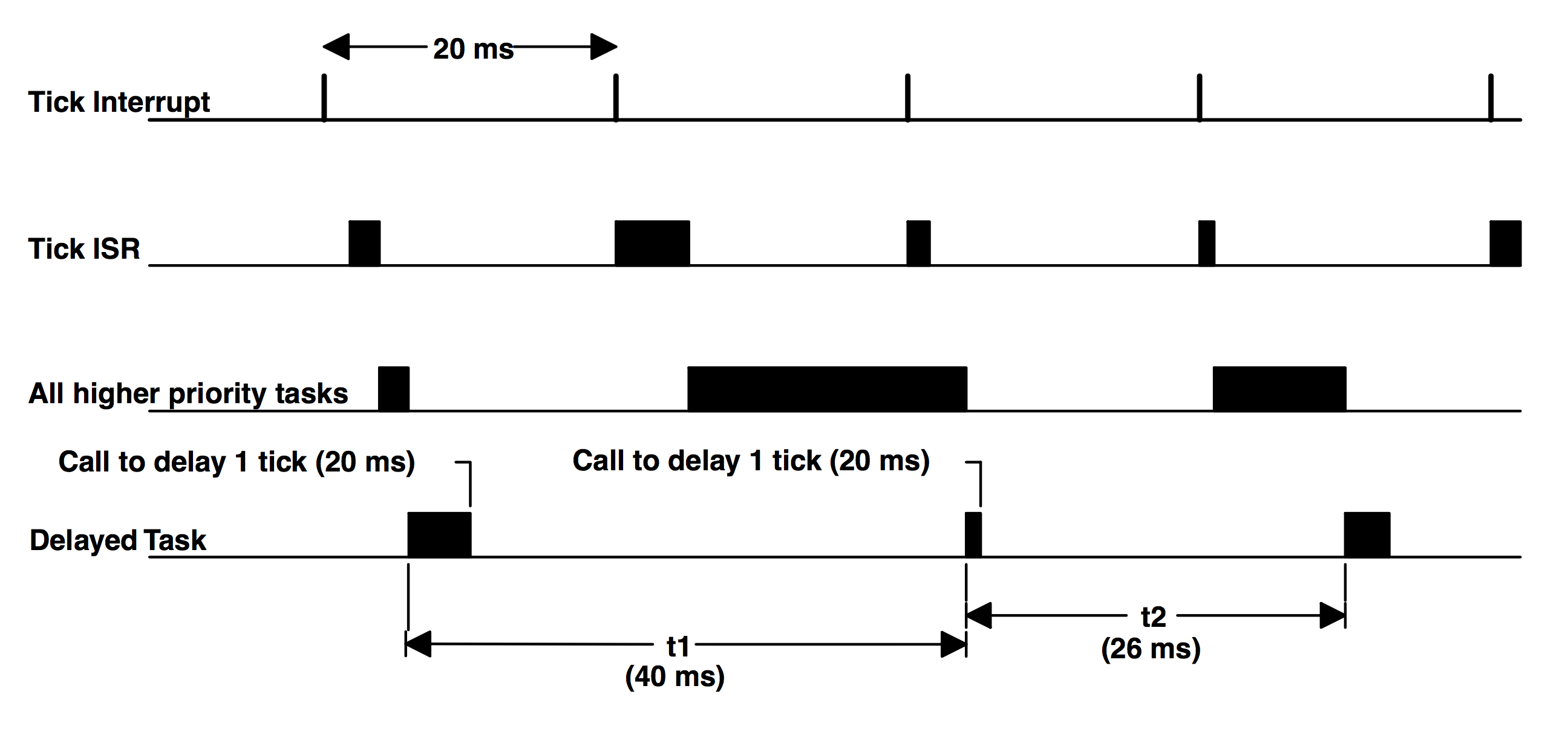
Case 3 (Figure 2.27) shows a situation in which the execution times of all higher priority tasks and ISRs extend beyond one clock tick. In this case, the task that tries to delay for one tick actually executes two ticks later and misses its deadline. This might be acceptable in some applications, but in most cases it isn’t.
These situations exist with all real-time kernels. They are related to CPU processing load and possibly incorrect system design. Here are some possible solutions to these problems:
- Increase the clock rate of your microprocessor.
- Increase the time between tick interrupts.
- Rearrange task priorities.
- Avoid using floating-point math (if you must, use single precision).
- Get a compiler that performs better code optimization.
- Write time-critical code in assembly language.
- If possible, upgrade to a faster microprocessor in the same family; that is, 8086 to 80186, 68000 to 68020, etc.
Regardless of what you do, jitter will always occur.
Memory Requirements
If you are designing a foreground/background system, the amount of memory required depends solely on your application code.With a multitasking kernel, things are quite different. To begin with, a kernel requires extra code space (ROM). The size of the kernel depends on many factors. Depending on the features provided by the kernel, you can expect anywhere from 1 to 100K bytes. A minimal kernel for an 8-bit CPU that provides only scheduling, context switching, semaphore management, delays, and timeouts should require about 1 to 3K bytes of code space. The total code space is given by Equation [2.12].
[2.12] Application code size + Kernel code size
Because each task runs independently of the others, it must be provided with its own stack area (RAM). As a designer, you must determine the stack requirement of each task as closely as possible (this is sometimes a difficult undertaking). The stack size must not only account for the task requirements (local variables, function calls, etc.), it must also account for maximum interrupt nesting (saved registers, local storage in ISRs, etc.). Depending on the target processor and the kernel used, a separate stack can be used to handle all interrupt-level code. This is a desirable feature because the stack requirement for each task can be substantially reduced. Another desirable feature is the ability to specify the stack size of each task on an individual basis (µC/OS-II permits this). Conversely, some kernels require that all task stacks be the same size. All kernels require extra RAM to maintain internal variables, data structures, queues, etc. The total RAM required if the kernel does not support a separate interrupt stack is given by Equation [2.13].
[2.13] Application code requirements
+ Data space (i.e., RAM) needed by the kernel itself
+ SUM(task stacks + MAX(ISR nesting))
If the kernel supports a separate stack for interrupts, the total RAM required is given by Equation [2.14].
[2.14] Application code requirements
+ Data space (i.e., RAM) needed by the kernel
+ SUM(task stacks)
+ MAX(ISR nesting)
Unless you have large amounts of RAM to work with, you need to be careful how you use the stack space. To reduce the amount of RAM needed in an application, you must be careful how you use each task’s stack for
- large arrays and structures declared locally to functions and ISRs,
- function (i.e., subroutine) nesting,
- interrupt nesting,
- library functions stack usage, and
- function calls with many arguments.
To summarize, a multitasking system requires more code space (ROM) and data space (RAM) than a foreground/background system. The amount of extra ROM depends only on the size of the kernel, and the amount of RAM depends on the number of tasks in your system.
Advantages and Disadvantages of Real-Time Kernels
A real-time kernel, also called a Real-Time Operating System, or RTOS, allows real-time applications to be designed and expanded easily; functions can be added without requiring major changes to the software. In fact, if you add low priority tasks to your system, the responsiveness of your system to high priority task will almost not be affected! The use of an RTOS simplifies the design process by splitting the application code into separate tasks. With a preemptive RTOS, all time-critical events are handled as quickly and as efficiently as possible. An RTOS allows you to make better use of your resources by providing you with valuable services, such as semaphores, mailboxes, queues, time delays, timeouts, etc.
You should consider using a real-time kernel if your application can afford the extra requirements: extra cost of the kernel, more ROM/RAM, and 2 to 4 percent additional CPU overhead.
The one factor I haven’t mentioned so far is the cost associated with the use of a real-time kernel. In some applications, cost is everything and would preclude you from even considering an RTOS.
There are currently about 100+ RTOS vendors. Products are available for 8-, 16-, 32-, and even 64-bit microprocessors. Some of these packages are complete operating systems and include not only the real-time kernel but also an input/output manager, windowing systems (display), a file system, networking, language interface libraries, debuggers, and cross-platform compilers. The development cost to use an RTOS varies from 0 USD (US Dollars) to well over 30,000 USD. The RTOS vendor may also require royalties on a per-target-system basis. Royalties are like buying a chip from the RTOS vendor that you include with each unit sold. The RTOS vendors call this silicon software. The royalty fee varies between 5 USD to more than 500 USD per unit. Like any other software package these days, you also need to consider the maintenance cost, which can set you back another 15% of the development cost of the RTOS per year!
Real-Time Systems Summary
Table 2.2 summarizes the three types of real-time systems: foreground/background, non-preemptive kernel, and preemptive kernel.
| Foreground / Background | Non-Preemptive Kernel | Preemptive Kernel | |
|---|---|---|---|
| Interrupt latency (Time) | MAX(Longest instruction, User int. disable) + Vector to ISR | MAX(Longest instruction, User int. disable, Kernel int. disable) + Vector to ISR | MAX(Longest instruction, User int. disable, Kernel int. disable) + Vector to ISR |
| Interrupt response (Time) | Int. latency + Save CPU’s context | Int. latency + Save CPU’s context | Interrupt latency + Save CPU’s context + Kernel ISR entry function |
| Interrupt recovery (Time) | Restore background’s context + Return from int. | Restore task’s context + Return from int. | Find highest priority task + Restore highest priority task’s context + Return from interrupt |
| Task response (Time) | Background | Longest task + Find highest priority task + Context switch | Find highest priority task + Context switch |
| ROM size | Application code | Application code + Kernel code | Application code + Kernel code |
| RAM size | Application RAM | Application RAM + Kernel RAM + SUM(Task stacks + MAX(ISR stack)) | Application RAM + Kernel RAM + SUM(Task stacks + MAX(ISR stack)) |
| Services available? | Application code must provide | Yes | Yes |