No-OS Interface
- Former user (Deleted)
- WES Admin
µC/Modbus-S can be configured to work in a single threaded environment (no RTOS needed).
The No-OS port uses the same RTOS interface layer provided by µC/Modbus. This layer is explained in Section 7.00.
Figure 8-1 shows a flow diagram of receive model in a environment that doesn’t use an RTOS.
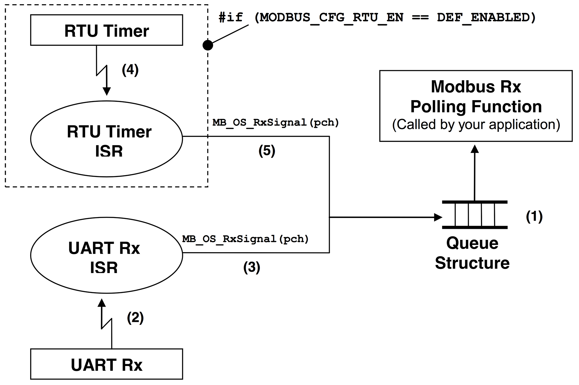
(1) µC/Modbus uses a queue structure indicating the channel that has received a packet. Your application must call MB_OS_RxTask() to poll the status of the queue, if the queue contains at least one element then this function will call MB_RxTask() which simply parses the packet and formulates a response that will be forwarded appropriately. The frequency at which the poling function is called is defined by your application.
(2) We assume that byte reception from a UART is interrupt driven. Received bytes are placed in a receive buffer until a complete packet is received. If the channel is configured for Modbus ASCII, an end of packet is signaled by a line feed character (i.e. 0x0A). If the channel is configured for Modbus RTU then the end of a packet is signaled by not receiving bytes for at least the time it takes to send 3.5 bytes (see Modbus RTU specification).
(3) Assuming Modbus ASCII, the end of a packet is signaled by calling MB_OS_RxSignal() and specifying a pointer to the channel on which a packet was received.
(4) If your product needs to support the Modbus RTU mode, you will need to provide a timer that interrupts the CPU in order to keep track of end of packets. Basically, when bytes are received on a channel, an RTU counter for that channel is reset to a value based on the baud rate of the channel (see the table below).
RTU Timeouts based on channel Baud Rate.
Baud Rate | RTU Timeout (Time for 3.5 Bytes) | RTU Timeout (Counts at 1 KHz) |
|---|---|---|
9,600 | 3646 µS | 5 |
19,200 | 1823 µS | 3 |
38,400 | 911 µS | 2 |
76,800 | 456 µS | 2 |
115,200 | 304 µS | 2 |
256,000 | 137 µS | 2 |
For example, if a channel is configured for 19,200 Baud then, an end of packet (in RTU mode) is assumed to occur when no bytes are received after 1800 µS (microseconds). If your RTU timer is setup to interrupt every millisecond then you would need roughly two such interrupts before you conclude that a packet was received. We decided to assume that a packet is received after at least the time it would take to receive 5.0 bytes instead of 3.5 bytes. Also, because of the asynchronous feature of the timer with respect to received bytes, we decided to count at least TWO RTU interrupts to conclude that a packet was received.
You can have better granularity for the timeout if you increase the RTU timer interrupt rate. However, this also increases the amount of overhead you are placing on your CPU.
(5) When the RTU timer interrupt occurs, the timeout counter for each of the channels that are configured for RTU mode are decremented. When a counter reaches 0, a signal is set to the ‘Modbus Rx Task’ for that channel. This tells the ‘Modbus Rx Task’ that a packet was received on that channel and needs to be processed. The signal is also performed by calling MB_OS_RxSignal().