RTOS Interface
- Former user (Deleted)
- WES Admin
µC/Modbus-S might use an RTOS interface, µC/Modbus-M assumes the presence of an RTOS but, it doesn’t assume any specific RTOS. In fact, µC/Modbus was designed to work with just about commercial RTOS by providing a simple RTOS interface layer.
µC/Modbus is provided with a µC/ModbusRTOS interface layer so you can start using µC/Modbus if you are also using µC/OS-II or µC/OS-III in your product or, use this interface layer as an example for your own RTOS.
Figure 7-1 shows a flow diagram of receive model.
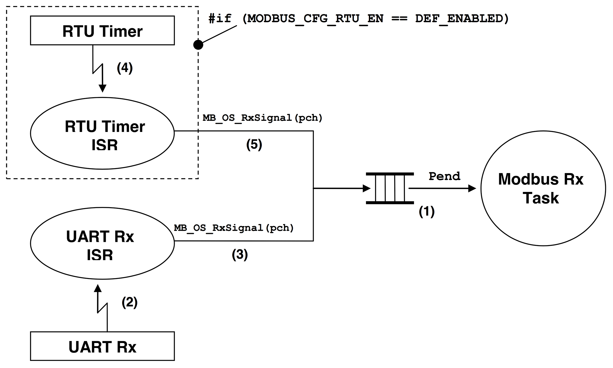
(1) µC/Modbus uses a single task to receive packets from any channel. The ‘Modbus Rx Task’ simply waits for a Modbus packet from any channel. Assuming µC/OS-II as the RTOS, a message queue is used for this purpose. For µC/OS-III, the message queue is built into the task. When a packet is received, a pointer to the channel that received the packet is posted to the message queue indicating to the ‘Modbus Rx Task’ which channel received the packet. The ‘Modbus Rx Task’ then simply parses the packet and formulates a response that will be forwarded appropriately.
(2) We assume that byte reception from a UART is interrupt driven. Received bytes are placed in a receive buffer until a complete packet is received. If the channel is configured for Modbus ASCII, an end of packet is signaled by a line feed character (i.e. 0x0A). If the channel is configured for Modbus RTU then the end of a packet is signaled by not receiving bytes for at least the time it takes to send 3.5 bytes (see Modbus RTU specification).
(3) Assuming Modbus ASCII, the end of a packet is signaled by calling MB_OS_RxSignal() and specifying a pointer to the channel on which a packet was received.
(4) If your product needs to support the Modbus RTU mode, you will need to provide a timer that interrupts the CPU in order to keep track of end of packets. Basically, when bytes are received on a channel, an RTU counter for that channel is reset to a value based on the baud rate of the channel (see the table below).
Baud Rate | RTU Timeout (Time for 3.5 Bytes) | RTU Timeout (Counts at 1 KHz) |
|---|---|---|
9,600 | 3646 µS | 5 |
19,200 | 1823 µS | 3 |
38,400 | 911 µS | 2 |
76,800 | 456 µS | 2 |
115,200 | 304 µS | 2 |
256,000 | 137 µS | 2 |
For example, if a channel is configured for 19,200 Baud then, an end of packet (in RTU mode) is assumed to occur when no bytes are received after 1800 µS (microseconds). If your RTU timer is setup to interrupt every millisecond then you would need roughly two such interrupts before you conclude that a packet was received. We decided to assume that a packet is received after at least the time it would take to receive 5.0 bytes instead of 3.5 bytes. Also, because of the asynchronous feature of the timer with respect to received bytes, we decided to count at least TWO RTU interrupts to conclude that a packet was received.
You can have better granularity for the timeout if you increase the RTU timer interrupt rate. However, this also increases the amount of overhead you are placing on your CPU.
(5) When the RTU timer interrupt occurs, the timeout counter for each of the channels that are configured for RTU mode are decremented. When a counter reaches 0, a signal is set to the ‘Modbus Rx Task’ for that channel. This tells the ‘Modbus Rx Task’ that a packet was received on that channel and needs to be processed. The signal is also performed by calling MB_OS_RxSignal().
In order to provide the RTOS functionality described above, you need to define three functions in a file called MB_OS.C:
MB_OS_Init()
MB_OS_Exit()
MB_OS_RxSignal()
MB_OS_RxWait()
MB_OS_Init()
This function is called by µC/Modbusto initialize the RTOS interface for the RTOS you are using. You would typically create the ‘Modbus Rx Task’ and setup the mechanism needed to signal this task when a packet is received or an RTU timeout occurred for the channel.
Prototype
void MB_OS_Init(void);
Arguments
None.
Returned Value
None.
Notes / Warnings
None.
Called By
MB_Init() in mb.c
MB_OS_Exit()
This function is called by MB_Exit() (see mb.c) to gracefully terminate the Modbus task. In the case of µC/OS-II, we would simply delete the ‘Modbus Rx Task’ and the message queue. In the case of µC/OS-III, we would simply delete the ‘Modbus Rx Task’ since the message queue is built into the task.
Prototype
void MB_OS_Exit(void);
Arguments
None.
Returned Value
None.
Notes / Warnings
None.
Called By
MB_Exit() in mb.c
MB_OS_RxSignal()
This function signals the reception of a complete packet. It is called by either the RTU timer interrupt for each channel that has not received characters within the timeout period or, by Modbus ASCII channels when a line feed character (i.e. 0x0A) is received.
Prototype
void MB_OS_RxSignal(MODBUS_CH *pch);
Arguments
pch
specifies a pointer to the Modbus channel data structure associated with the received packet.
Returned Value
None.
Notes / Warnings
None.
Called By
MB_RTU_TmrUpdate() or MB_ASCII_RxByte() in mb.c
MB_OS_RxWait()
This function waits for a response from a slave. MB_OS_RxWait() is called from a Modbus master task after it sent a command to a slave and is waiting for a response. If the response is not received within the timeout specified when the channel was configured (see MB_CfgCh()) then this function returns to the caller and notifies it of the timeout.
Prototype
void MB_OS_RxWait(MODBUS_CH *pch, CPU_INT16U *perr);
Arguments
pch
specifies a pointer to the Modbus channel data structure associated with the received packet.
perr
is a pointer to an error code indicating the outcome of the call and can be one of the following errors:
MODBUS_ERR_NONE
the call was successful
MODBUS_ERR_TIMED_OUT
A response was not received within the specified timeout.
MODBUS_ERR_NOT_MASTER
You called this function from a non-master channel
MODBUS_ERR_INVALID
An invalid error occurred. Refer to MB_OS.C for details.
Notes / Warnings
None.
Called By:
MBM_FC??_???() in MBM_CORE.C
Configuration
If you use µC/OS-II, you need to configure the following #define constants:
OS_Q_EN
The size needs to be as large as the number of Modbus channels.
OS_SEM_EN
If you use Modbus Master, you need to enable semaphore services.
MB_OS_CFG_RX_TASK_ID
MB_OS_CFG_RX_TASK_PRIO
MB_OS_CFG_RX_TASK_STK_SIZE
If you use µC/OS-III, you need to configure the following #define constants:
OS_CFG_Q_EN
The size of the message queue will be set to the number of channels (i.e. MODBUS_CFG_MAX_CH) in mb_os.c.
OS_CFG_SEM_EN
If you use Modbus Master, you need to enable semaphore services.
MB_OS_CFG_RX_TASK_PRIO
MB_OS_CFG_RX_TASK_STK_SIZE
These constants need to be defines in you application.