Introduction
- Former user (Deleted)
- WES Admin
This document describes µC/Modbus, which implements the Modicon Modbus Protocol (referred to as Modbus) along with the “Daniel’s Extension” to the Modbus protocol, as specified by Daniel Flow Products.
For more details on the Modbus protocol, please refer to Modicon’s:
Modicon Modbus Protocol Reference Guide (PI–MBUS–300 Rev. J)
The Modbus protocol consists of the reception and transmission of data, in predefined packets, hereby referred to as “frames”. There are two types of frames that the Modbus protocol operates with, an ASCII frame, and a Remote Terminal Unit (RTU) frame. The ASCII frame is a frame based on ASCII hexadecimal characters, while the RTU frame is strictly a binary implementation. ASCII mode is easier to implement and debug but offers roughly half the data transfer speed of RTU mode. With µC/Modbus you can use either mode since implementation and testing has been done by Micrium.
µC/Modbus can support any number of communication channels. The mode of operation on each channel can either be ASCII or RTU and is selectable on a per ‘channel’ basis.
The figure below shows the relationship between a product designed using µC/Modbus and other Modbus masters and slaves products. The ‘Serial Channels’ are typically RS-232C or RS-485 asynchronous serial interfaces typically using a UART (Universal Asynchronous Receiver Transmitter).

Masters (also known as Clients) initiate all data transfers to one or more Slaves (also known as Servers) in a system. In other words, only a Master (Client) can read or write values from/to a Slave (Server).
µC/Modbus can be made to look like having multiple master or slave ports. In fact, µC/Modbus allows you to have a combination of up to 250 master or slave ports from a single target system!
µC/Modbus-S indicates that your product contains the Modbus slave implementation of µC/Modbus and, µC/Modbus-M indicates that your product contains the Modbus master implementation of µC/Modbus.
You should note that a product can contain both µC/Modbus-S and µC/Modbus-M at the same time. However, the master and the slave would be on separate ports.
Topologies
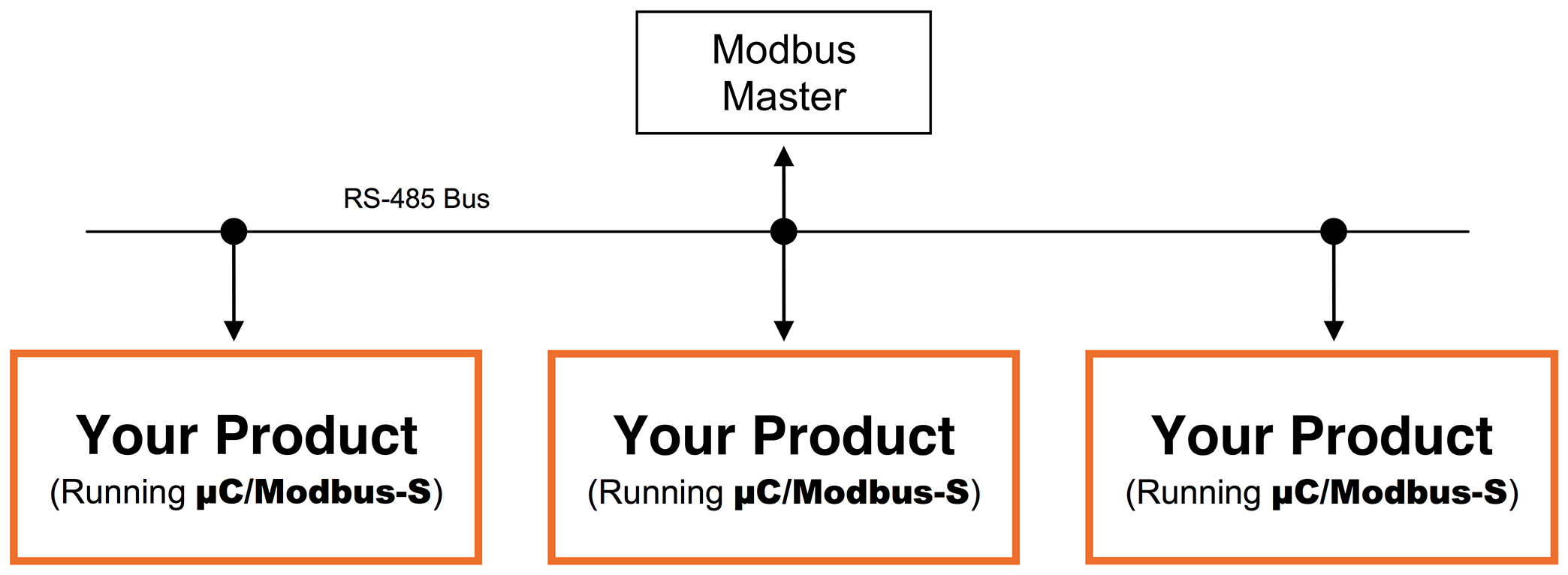
The figure below shows the relationship between multiple products (slaves) and a Modbus master (assuming RS-485).
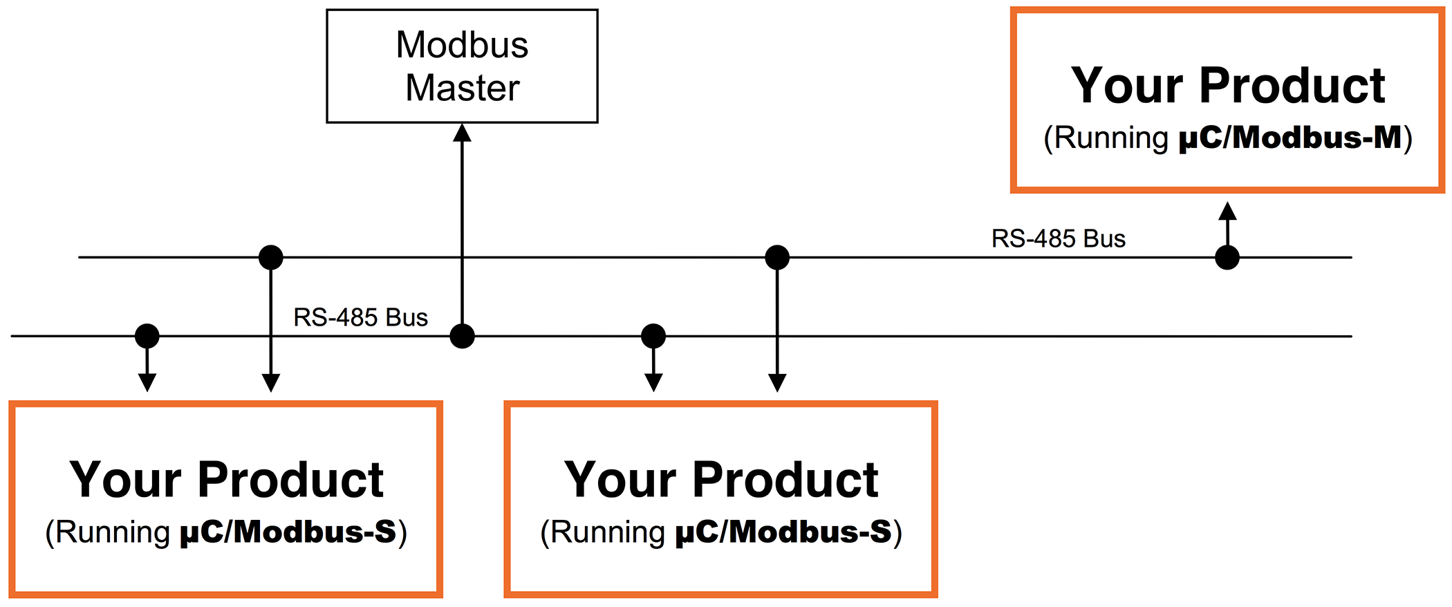
The figure below shows the relationship between multiple products (slaves) and multiple Modbus masters (assuming RS-485 in the example) with one of those products being µC/Modbus-M. You will note that only one master can be present on each RS-485 network.
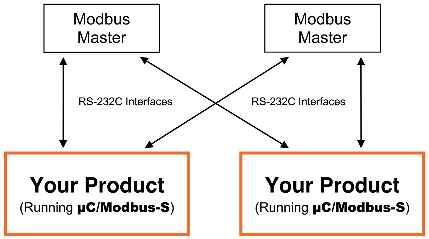
The figure below shows the relationship between multiple products (slaves) and multiple Modbus masters (assuming RS-232C in the example). As you can see, with RS-232C, each master needs to have a direct connection to each slave. µC/Modbus supports this topology since each product can have multiple communication channels. Although RS?232C requires more point-to-point connections, it offers the benefit of higher throughput since communications can occur concurrently instead of sequentially.
Modbus allows you to read or write integer, floating-point (assuming the Daniels Extensions) and discrete values from/to your target system. µC/Modbus can read or write from/to:
up to 65536 16-bit integer values,
up to 65536 32-bit floating-point values,
up to 65536 coils, and
up to 65536 discrete inputs.
Integer and floating-point requests may not be mixed in the same command. Multiple integer values (up to 125) and multiple floating-point values (up to 62) may be written via a single command.
Depending on the processor you are using, you should be able to run µC/Modbus with data rates from 9600 up to 256,000 baud. The baud rate you can attain is actually limited to the performance of the CPU and not µC/Modbus.
µC/Modbus Architecture
Figure 1-5 shows how the µC/Modbus communications stack fits in your product and also shows which source files are associated with each layer.
MB stands for ModBus, MBS stands for ModBus Slave and MBM stands for ModBus Master. A file that starts with mb_ indicates that the code in the file is independent of Modbus Slave or Master. A file that starts with mbs_ contains Modbus Slave specific code and, of course, a file that will start with mbm_ will contain MODBUS Master specific code.
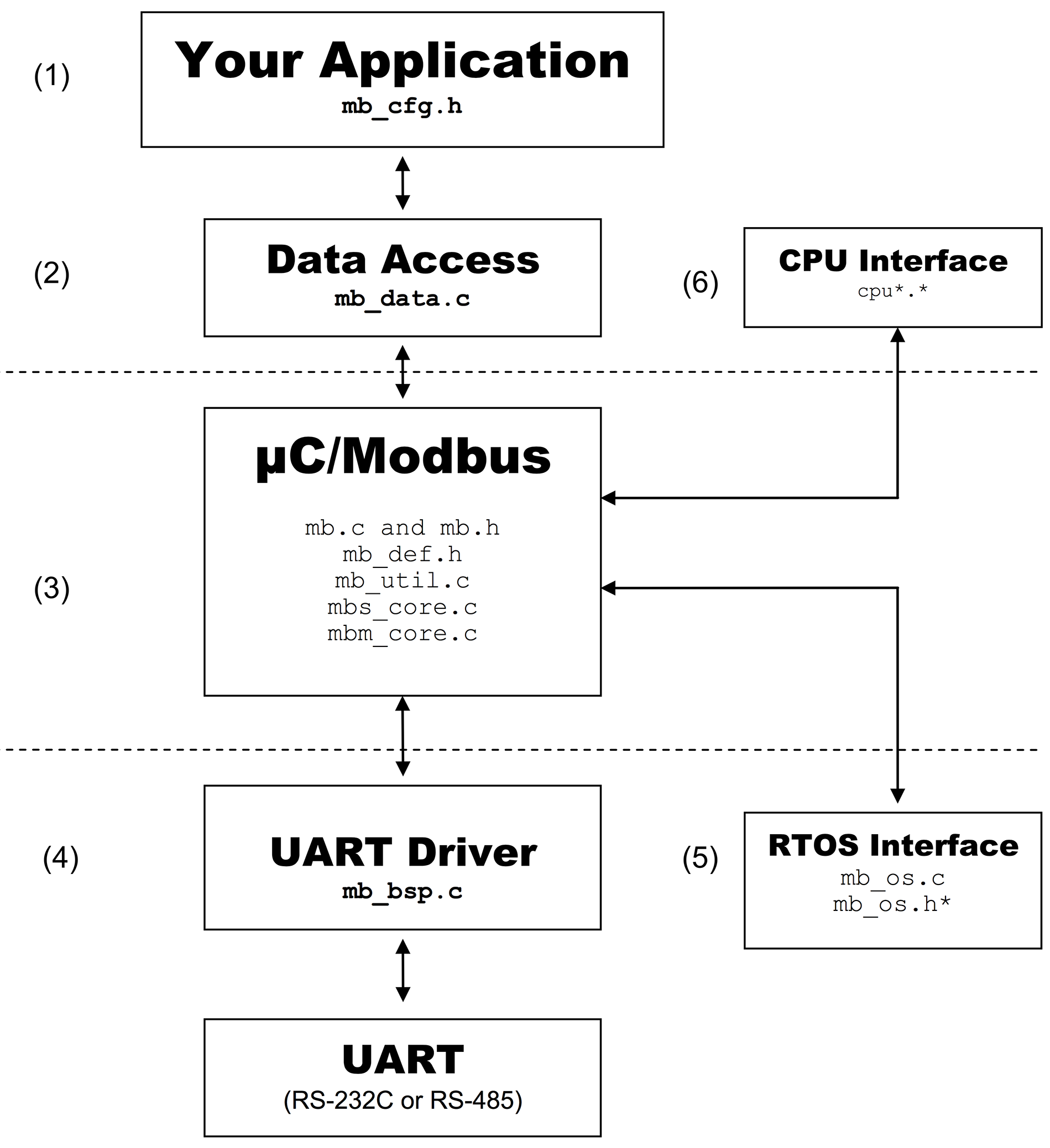
(1) Your product needs to configure µC/Modbus (at compile time) to establish the maximum number of channels your product will support, whether some channels will support Modbus ASCII and/or RTU, whether the ‘Daniels Extensions’ will be supported to provide floating-point, which Modbus function codes will be supported, whether a product will be a Master, a Slave or both, etc. Configuration is done by changing a C header file (mb_cfg.h). This is code that YOU need to provide and mb_cfg.h typically resides in your product’s directory since it can be different for each product.
(2) A Modbus master, connected to your product (that is running µC/Modbus-S) can read or change just about ANY data in your application. Access to your data (read or write) is done via a C file that you provide (mb_data.c). mb_data.c can read integers, coils, discrete inputs, floating-point values, etc. mb_data.c also allows you to execute ANY code when data is read or written. For example, if you change the diameter of a circle and need to compute the surface, you can simply include the code to compute the surface in mb_data.c. More on this later. This is code that YOU need to provide and mb_data.c typically resides in your product’s directory since it can be different for each product.
(3) This is the application independent slave code and it knows how to process Modbus ASCII and/or Modbus RTU packets. You should NOT have to modify this code.
(4) The interface to the UARTs in your product is placed in the Board Support Package (BSP) file called mb_bsp.C. This is a file that you provide in order to interface to µC/Modbus. Note that each channel can either communicate via RS-232C or RS-485 (at the interface level). This is code that YOU need to provide and mb_bsp.c is either placed in your product’s directory or provided by Micrium in the
\Micrium\Software\uC-Modbus\Ports\<CPU>\<compiler>
directory. This is the adaptation layer for the CPU or board you are using.
(5) µC/Modbus-S can be used with or witouth a RTOS (Real Time Operating System) eviroment. µC/Modbus-M assumes the presence of an RTOS. However, you can use just about any RTOS and the RTOS specifics are actually isolated in a file called mb_os.c. The code for µC/OS-II, µC/OS-III and Non-OS environment are provided so you don’t have to change this code if you use µC/OS-II or µC/OS-III in your product or you use µC/Modbus-S witouth any RTOS. The file mb_os.h. is only needed when µC/Modbus-S is used witouth any RTOS this is explained in Section 8.
(6) µC/Modbus is independent of the CPU and the compiler you use. However, you need to provide information about the data types specific to your CPU and compiler. For example, you need to define the following data types:
CPU_BOOLEAN Boolean (True or False, Yes or No, etc.)
CPU_INT08U  8 bit unsigned integer
CPU_INT16U  32 bit unsigned integer
CPU_INT32U  8 bit unsigned integer
CPU_FP32    32 bit IEEE754 floating-point
Etc.
These data types are needed because µC/Modbus never uses the standard C data types (i.e. char, short, int, long, etc.) because they are non-portable.
These data types need to be placed in a file called cpu.h (more on this later).