...
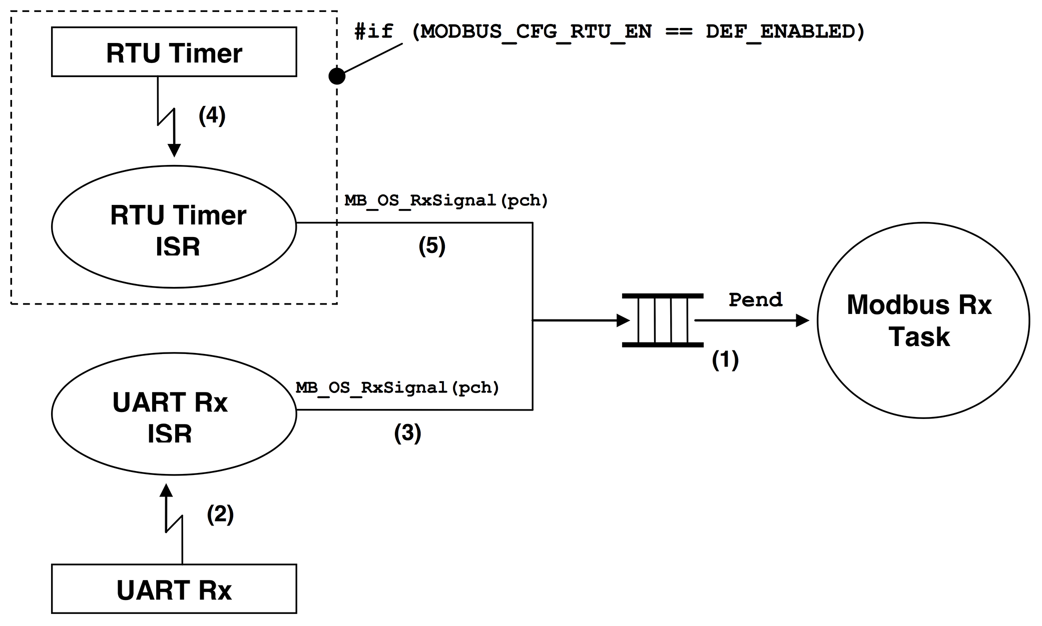
Figure 7-1 shows a flow diagram of receive model.
| Panel | ||||
|---|---|---|---|---|
| ||||
|
| Panel | |||||||||||||||||||||
|---|---|---|---|---|---|---|---|---|---|---|---|---|---|---|---|---|---|---|---|---|---|
| |||||||||||||||||||||
(1) µC/Modbus uses a single task to receive packets from any channel. The ‘Modbus Rx Task’ simply waits for a Modbus packet from any channel. Assuming µC/OS-II as the RTOS, a message queue is used for this purpose. For µC/OS-III, the message queue is built into the task. When a packet is received, a pointer to the channel that received the packet is posted to the message queue indicating to the ‘Modbus Rx Task’ which channel received the packet. The ‘Modbus Rx Task’ then simply parses the packet and formulates a response that will be forwarded appropriately. (2) We assume that byte reception from a UART is interrupt driven. Received bytes are placed in a receive buffer until a complete packet is received. If the channel is configured for Modbus ASCII, an end of packet is signaled by a line feed character (i.e. (3) Assuming Modbus ASCII, the end of a packet is signaled by calling (4) If your product needs to support the Modbus RTU mode, you will need to provide a timer that interrupts the CPU in order to keep track of end of packets. Basically, when bytes are received on a channel, an RTU counter for that channel is reset to a value based on the baud rate of the channel (see the table below).
For example, if a channel is configured for 19,200 Baud then, an end of packet (in RTU mode) is assumed to occur when no bytes are received after 1800 µS (microseconds). If your RTU timer is setup to interrupt every millisecond then you would need roughly two such interrupts before you conclude that a packet was received. We decided to assume that a packet is received after at least the time it would take to receive 5.0 bytes instead of 3.5 bytes. Also, because of the asynchronous feature of the timer with respect to received bytes, we decided to count at least TWO RTU interrupts to conclude that a packet was received. You can have better granularity for the timeout if you increase the RTU timer interrupt rate. However, this also increases the amount of overhead you are placing on your CPU. (5) When the RTU timer interrupt occurs, the timeout counter for each of the channels that are configured for RTU mode are decremented. When a counter reaches In order to provide the RTOS functionality described above, you need to define three functions in a file called
|
MB_OS_Init()
This function is called by µC/Modbusto initialize the RTOS interface for the RTOS you are using. You would typically create the ‘Modbus Rx Task’ and setup the mechanism needed to signal this task when a packet is received or an RTU timeout occurred for the channel.
...